
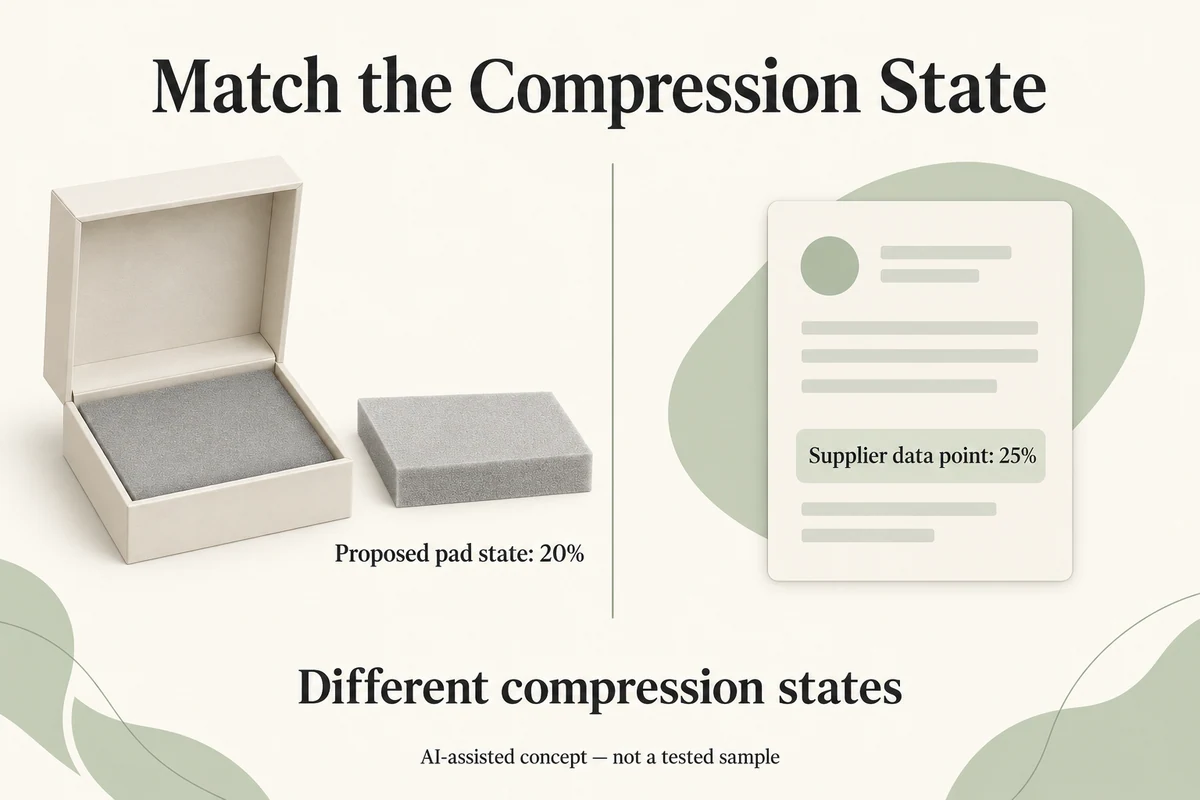
A foam compression value is useful for a jewelry holder proposal only when it describes the compression state the design is expected to create. If a supplier’s technical sheet reports compression at 25% deflection, but the proposed pad would be compressed by 20%, those are different states. The 25% value cannot simply be relabeled or proportionally adjusted to answer the 20% question.
For a small jewelry or gift brand, the immediate decision is not which foam is best. It is whether the available compression data can support a comparison at the intended deflection.
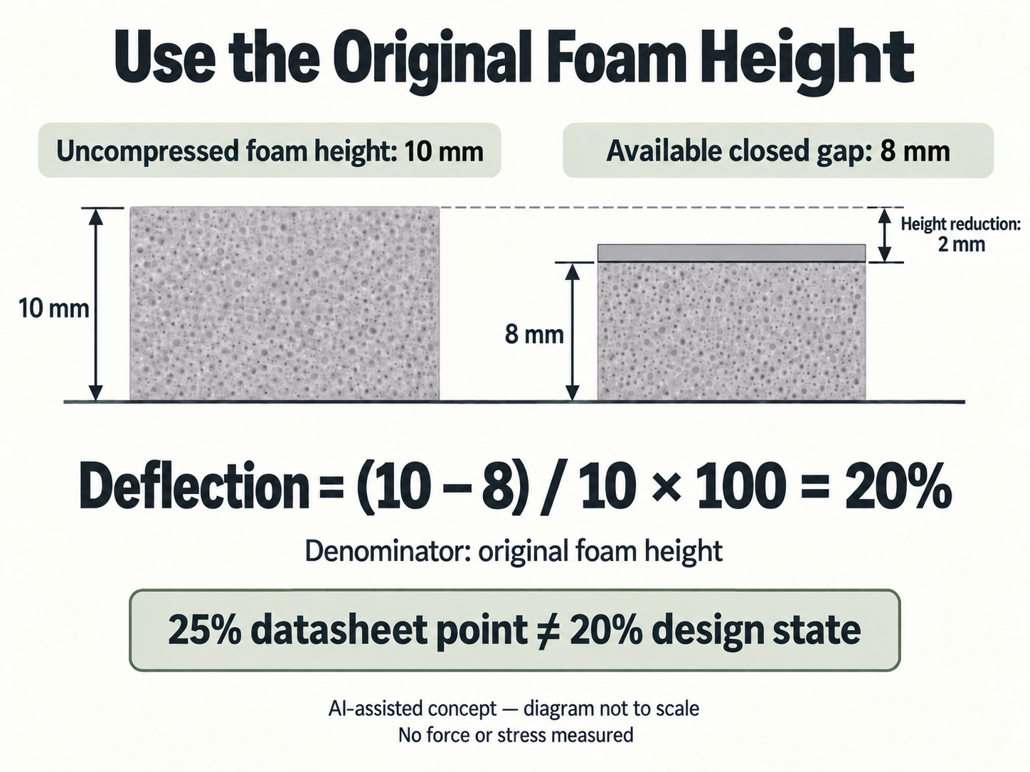
Calculate deflection from the original foam height
Compression deflection describes how much a material’s height decreases relative to its original, uncompressed height.
Consider a purely hypothetical flat foam pad:
- Uncompressed foam height: 10 mm
- Available gap when the package is closed: 8 mm
- Reduction in height: 2 mm
Assuming the pad is compressed uniformly between two flat surfaces, its relative deflection is:
Deflection (%) = (Original height − Compressed height) ÷ Original height × 100
(10 − 8) ÷ 10 × 100 = 20%
The denominator is the original 10 mm foam height, not the remaining 8 mm gap. Dividing 2 mm by 8 mm would incorrectly describe this example as 25% compression.
This distinction matters because compression data is commonly associated with a particular percentage of the original specimen thickness.
Now imagine the same uncompressed pad in a different enclosure. If the available gap becomes 7.5 mm, the nominal deflection becomes 25%. If it becomes 9 mm, the nominal deflection becomes 10%.
These calculations identify geometric states. They provide no compression force, stress, safe contact pressure, or material recommendation.
The example also assumes that 10 mm describes the foam itself. If a proposal includes a separate backing, adhesive or other relatively noncompressible layer, the buyer must establish the actual foam thickness and the clearance available to that foam. Total assembly thickness should not automatically become the denominator.
Match the supplier data to the calculated percentage
A supplier might provide a technical data sheet containing one compression value measured at 25% deflection.
For the hypothetical 10 mm pad installed in an 8 mm gap, that is not the target state. The design calculation identifies 20% nominal deflection, while the supplied value describes 25%.
The distinction follows the measurement explanation in Rogers Corporation’s guide to compression force deflection, published November 12, 2024. Its discussion of percentage deflection and compression response concerns elastomeric materials, particularly sealing and gasketing applications.
The useful principle for a gift-packaging buyer is narrower: identify which percentage of compression the reported value actually represents.
If the manufacturer provides a relevant curve covering 20% deflection, the buyer can identify the corresponding position on that curve for technical review. If the sheet supplies only a 25% point, the response at 20% remains unsupported by that point alone.
Even when a datasheet’s percentage matches the calculated percentage, the material identity and test basis must still be checked before the value is considered applicable.
Read the reported quantity and its unit
The words compression force deflection can be misleading when the actual technical result is expressed as stress rather than total force.
A compression result might be reported as:
- Stress or pressure: for example, kPa or psi.
- Force: for example, N or lbf.
- Relative deflection: a percentage of the original specimen height.
These quantities answer different questions.
A stress value describes force relative to an area under the stated test conditions. A force value describes the total applied force for the specified test arrangement. Neither should be read without its unit and specimen information.
For example, a result whose vertical axis is labeled kPa cannot be treated as a total force in newtons. Converting stress into a force estimate would require an appropriate loaded area and a valid relationship between the test and the intended loading arrangement.
Rogers’ January 17, 2025 article, Foam Firmness vs Density and Why Its Important, explains foam compression behavior using stress and strain. It also identifies ASTM D1056 for its BISCO silicone materials and ASTM D3574 for its PORON polyurethane materials.
Those are manufacturer-specific material and testing references, not interchangeable test procedures or universal requirements for jewelry packaging.
The buyer should therefore preserve the exact reported quantity, unit, method and material identity. The CFD abbreviation alone does not establish what the numerical value means.
A nonlinear curve prevents simple proportional estimates
Suppose the supplier reports compression behavior at 25%, but the intended geometry implies 20%.
It may be tempting to multiply the reported value by 20/25 and use the result as an estimate.
That is not a justified general calculation.
Foam compression response can be nonlinear. The relationship between deflection and resistance may change as the cellular structure compresses, and a curve can become steeper over part of its range.
Rogers explicitly discusses this nonlinear behavior in its 2024 compression guide. Its illustrated comparisons also emphasize using the same specimen thickness when comparing material curves.
A single 25% data point does not establish the response at 20%. Nor does a nominally similar product name establish that a curve from another grade applies.
A defensible comparison needs suitable grade-specific information at or covering the intended deflection, interpreted within its declared measurement basis. Numerical interpolation or extrapolation should not be introduced without technical support appropriate to that material and curve.
When reviewing a curve, the relevant questions are whether it represents the proposed grade and thickness, how its axes and units are defined, and what measurement method and conditions apply. If loading history or another test condition matters to the comparison, its basis should also be established.
The manufacturer data helps define a material response under its stated conditions. It does not automatically predict the behavior of a finished jewelry holder.
A shaped jewelry cavity changes the loading geometry
A flat compression specimen and a finished foam jewelry holder are not the same mechanical arrangement.
Consider a holder with a cut opening for a ring. The surrounding foam may have different remaining widths, depths and supporting surfaces. A product may touch only selected locations rather than compressing a uniform, continuous pad.
A backing layer may carry part of the load. A cut edge may bend rather than undergo uniform through-thickness compression. The closed box may also create different clearances at different locations.
As a result, the nominal 20% calculation for a flat pad does not establish a uniform 20% compression throughout a shaped holder.
It also cannot determine the local pressure applied to a ring, gemstone setting, plated surface or delicate finish.
The separate Packrivo guide to foam fabrication and layer proposals addresses the physical construction needed to define such a holder. The insert-material guide addresses form, fit and product contact.
Neither question should be replaced with an unsupported force calculation from a flat-specimen datasheet.
Conditions may also affect how measurements are compared. Packrivo’s sample-conditioning guide explains why preparation and environmental histories should remain identifiable rather than being assumed equivalent.
Actual product-contact suitability, recovery after compression and transport cushioning performance remain separate evaluations. A compression curve alone does not establish any of them.
Record the compression-state evidence decision
Return to the hypothetical flat pad with a 10 mm uncompressed height and an 8 mm available gap.
The useful buyer decision is:
Intended nominal deflection: 20%. Available supplier data: 25% compression point. Evidence status: the supplied point does not directly describe the intended state.
The next request should identify the proposed foam grade, the compressible thickness in the actual component, and data for that grade at or covering the intended 20% deflection. The response should state whether the result represents stress or force, its unit, and the applicable specimen, method and conditions.
If a complete relevant curve is available, its 20% region can be reviewed without inventing a new value. If no suitable data is available, record the compression response at 20% as unknown rather than treating the 25% point as an answer.
If the assembly changes to a nominal 7.5 mm gap, the geometric calculation changes to 25%. The existing 25% point then aligns in percentage, but still requires checks of material identity, thickness, test basis and actual holder loading geometry.
This is the boundary of the decision. The buyer can establish whether the proposed design state and supplied compression evidence correspond. That comparison does not itself establish a suitable foam grade or an acceptable force on the jewelry.
For a Packrivo sourcing and project-coordination discussion, the practical output is a precise missing-data question tied to the proposed component, rather than an unsupported material approval.
Subtract a separate backing before calculating foam deflection
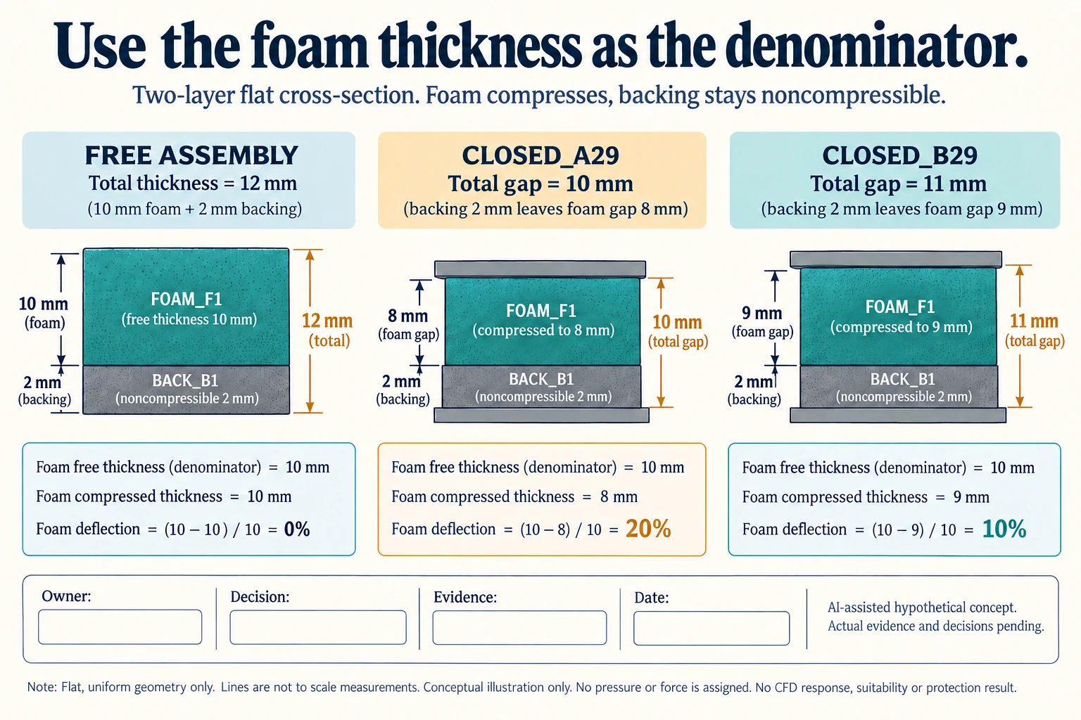
Add an explicitly noncompressible backing to a new flat-pad exercise. FOAM_F1 has an assumed free thickness of 10 mm; BACK_B1 is assumed 2 mm and unchanged under this geometry. The free assembly is 12 mm. CLOSED_A29 offers a 10 mm total gap for both layers, leaving 10 − 2 = 8 mm for the foam. Its nominal foam reduction is 2 mm, and its deflection is 2 ÷ 10 = 20%.
Scroll horizontally if columns extend beyond the view.
| Hypothetical configuration | Named object | Relationship | Input or next scope |
|---|---|---|---|
| LAYERS29 | FOAM_F1 | assumed input | 10 mm |
| LAYERS29 | BACK_B1 | assumed input | 2 mm |
| LAYERS29 | ASSEMBLY | calculated from | FOAM_FREE+BACKING; 12 mm |
| CLOSED_A29 | ASSEMBLY_GAP | assumed input | 10 mm |
| CLOSED_A29 | FOAM_F1 | calculated from | CLOSED_A29_TOTAL_GAP-BACKING; 8 mm |
| CLOSED_A29 | FOAM_F1 | calculated from | FOAM_FREE-CLOSED_A29_FOAM_GAP; 2 mm |
| CLOSED_A29 | FOAM_F1 | calculated from | CLOSED_A29_REDUCTION/FOAM_FREE*100; 20 percent |
| CLOSED_B29 | ASSEMBLY_GAP | assumed input | 11 mm |
| CLOSED_B29 | FOAM_F1 | calculated from | CLOSED_B29_TOTAL_GAP-BACKING; 9 mm |
| CLOSED_B29 | FOAM_F1 | calculated from | CLOSED_B29_REDUCTION/FOAM_FREE*100; 10 percent |
| LAYERS29 | BACK_B1 | assumed | NONCOMPRESSIBLE_UNCHANGED_AND_UNIFORM_FLAT_LOADING |
| LAYERS29 | GEOMETRY | does not supply | CFD_FORCE_PRESSURE_OR_SUITABILITY |
Dividing the same 2 mm reduction by the 12 mm free assembly would give about 16.67%, but that answers the wrong denominator for the stated foam-only compression. The backing has not become compressible foam. CLOSED_B29 instead offers an 11 mm total gap, leaving 9 mm for F 1 and giving 10% nominal deflection. Both calculations depend on the declared unchanged backing and uniform flat loading, not on an actual measured stack.
The worksheet links total gap, backing thickness, remaining foam gap and foam free thickness, so a changed layer can be traced to the affected calculation. If adhesive, flock, an additional film or a compressible backing is introduced, the two-layer premise is incomplete. Leave the applicable clearances open until the offered construction explains them. A rounded assembly thickness on a quotation cannot fill the missing foam thickness.
Neither geometry supplies a CFD response. A manufacturer’s 25% point does not directly answer either 20% or 10%; no proportional scaling of that point is used. Obtain appropriate grade/thickness data with a named force or pressure quantity, unit, method and conditions. The original Rogers sources concern their material explanations and sealing/gasket examples, not a packaging-protection or jewellery-contact approval. A cavity or partial contact can also invalidate the flat, uniform geometry assumed here.
Download the foam backing thickness available gap compression calculation record (.csv). It includes the original table fields and scenarios alongside the added relationships. HYPOTHETICAL rows are editorial examples or required review scopes, not actual records. Actual quantity, configuration, component and file identities, materials, process, specification, copy, method, condition, observation, owner, decision, evidence and dates are blank. ACTUAL_BLANK is a separate empty starting row; enter permitted project evidence before using an actual record. A blank means unknown.
Use the Foam Packaging Inserts: Fabrication and Layer Scope for its separate question.
Source scope checked 17 October 2026: Rogers articles dated 12 November 2024 and 17 January 2025 explain their material response and sealing/gasket contexts. Mentioned ASTM methods were not acquired or run; the invented flat-layer geometry establishes no force, pressure, holder suitability, protection or lifetime. The added configurations and calculations are hypothetical, with actual evidence and decisions pending.
Discuss this packaging specification with Packrivo. We coordinate independent suppliers. MOQ: 500 pieces per product/design; illustrative quantities are not production offers. Confirm materials, samples, price and timing for your project.