
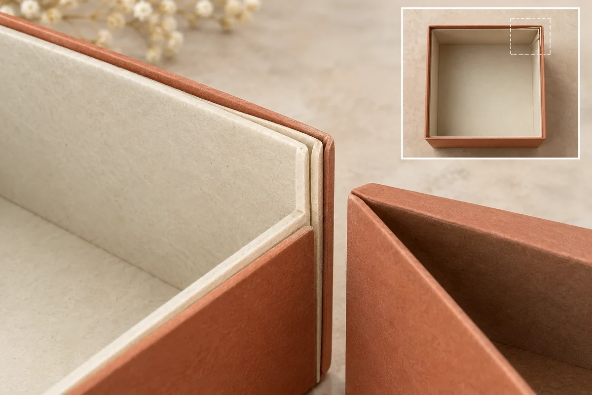
Mark proposed liner corner overlaps before checking usable space in a loaded box. Show the local layers and the product position at each relevant corner. An outside box dimension or a flat liner drawing leaves the formed corner interface unresolved.
The useful output is a local section and a measurement-state note. It helps separate a corner question from a request to change every inside dimension.
Identify the proposed overlap
The box-liner reference identifies lining along box walls. Ask the supplier to show how its actual liner meets or overlaps at the corners. The catalogue does not establish one universal corner construction.
Name the corner positions and the layers present. Keep the liner, outer box and any wrap distinct in the section. Record whether the sample represents the final material and formed state.
Mark a common datum for any measurement. Use the dimension acceptance method when the reading will become an acceptance criterion, including instrument and agreed state.
Map local space against the product
Place the complete product or holder in the proposed orientation. Show the corner or edge nearest the overlap. A local raised area can create an interface different from the main wall’s clear span.
Record the actual point measured or observed rather than a general interior-size label. If a folded layer is present only at one corner, preserve that local difference in the map.
| Corner record | Input | Evidence |
|---|---|---|
| Position ID | Named box corner and reference face | Top/side location view |
| Layer build | Proposed overlapping parts | Supplier section or sample detail |
| Measurement state | Formed, lined and loaded condition | Method and datum |
| Product relationship | Nearest complete envelope point | Located contact view |
| Other corners | Same or different construction | Separate observations |
| Revision | Changed layer or geometry | Affected corner recheck |
Do not average a local corner observation into a universal cavity value without an agreed method. Name what was actually measured.
Follow a hypothetical lined gift tray
Suppose a gift holder fits along the middle of a lined box but meets a proposed overlap at one rear corner. The buyer names that corner C3 and the holder point HP3, retaining the complete installed view.
The supplier is asked to show C3’s layer build and assess its relationship to HP3. A general outside-size reply leaves the local issue open. The buyer does not enlarge the whole box immediately.
If the proposal changes the liner joint, record that as a component change. If it changes the holder, keep that separate. The next sample should identify which interface is being compared.
Keep local evidence traceable
A useful question is: ‘Please confirm the finished layer build at C3 and the agreed way to review HP3 clearance.’ It names the location and required response without inventing a tolerance.
If another corner has the same proposed build, document its actual view before carrying the observation across. A drawing can show intended symmetry while assembly still needs its own evidence.
This original sketch locates dimensional and contact questions. It does not establish retention, protection or a universal liner thickness. Any such requirement needs a defined responsible review.
Send the corner section
Bring the local layer view, product point and measurement-state record through Packrivo’s enquiry. The next response should confirm the actual corner construction and identify the relevant revised evidence.
Compare local corner deductions without averaging the cavity
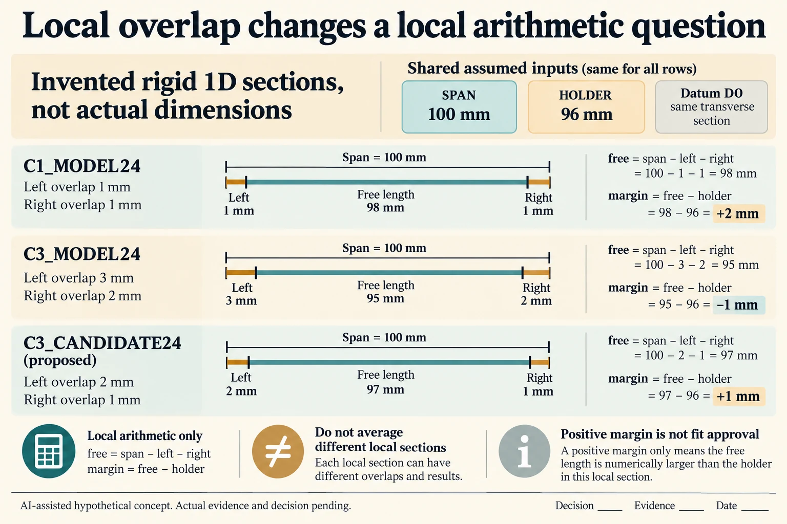
Use a deliberately simplified, rigid one-dimensional section with a common transverse datum D0. Assume an unlined span of 100 mm and a holder width of 96 mm at the same section. At location C1, hypothetical left and right liner deductions are 1 mm each. The modeled free span is 98 mm and the signed difference from the holder is +2 mm. These are invented inputs, not measured layers, recommended allowances or supplier tolerances.
Scroll horizontally if columns extend beyond the view.
| Hypothetical configuration | Named object | Relationship | Input or next scope |
|---|---|---|---|
| C1_MODEL24 | LEFT | assumed local input | C1; 1 mm |
| C1_MODEL24 | RIGHT | assumed local input | C1; 1 mm |
| C1_MODEL24 | FREE | calculated from | SPAN-LEFT-RIGHT; 98 mm |
| C1_MODEL24 | MARGIN | calculated from | FREE-HOLDER; 2 mm |
| C3_MODEL24 | LEFT | assumed local input | C3; 3 mm |
| C3_MODEL24 | RIGHT | assumed local input | C3; 2 mm |
| C3_MODEL24 | FREE | calculated from | SPAN-LEFT-RIGHT; 95 mm |
| C3_MODEL24 | MARGIN | calculated from | FREE-HOLDER; -1 mm |
| C3_CANDIDATE24 | LEFT | assumed local input | C3_REVISED; 2 mm |
| C3_CANDIDATE24 | RIGHT | assumed local input | C3_REVISED; 1 mm |
| C3_CANDIDATE24 | FREE | calculated from | SPAN-LEFT-RIGHT; 97 mm |
| C3_CANDIDATE24 | MARGIN | calculated from | FREE-HOLDER; 1 mm |
At the hypothetical C3 section, deductions of 3 mm left and 2 mm right leave 95 mm, giving a signed margin of −1 mm against the same 96 mm holder. A proposed C3 joint uses 2 mm and 1 mm deductions, leaving 97 mm and +1 mm. Each input and output has its own CSV row, formula and input references. C1, C3 and the revised C3 are three located comparisons, not values to average into a single usable cavity width.
The arithmetic assumes those deductions describe the relevant opposing surfaces at one height and direction, with no compression or deformation. It cannot be applied to a curved or differently oriented holder by reading an outside box width. A positive modeled margin does not establish insertion, grip, retention or protection; a negative signed value only identifies overlap within this assumed section model. The actual complete envelope, local section and agreed measurement method remain necessary.
Keep a liner-joint revision separate from a holder revision. If a changed section also moves the holder or changes the reference faces, replace the corresponding inputs before comparing it. PackMojo identifies liner components but supplies no universal corner construction. Actual material, folds and formed layers must come from the offered drawing and sample; the worksheet leaves all actual readings and acceptance fields blank.
Download the liner corner local space model record (.csv). It includes the original table fields and scenarios alongside the added relationships. HYPOTHETICAL rows are editorial examples or required review scopes, not actual records. Actual quantity, configuration, component and file identities, materials, process, specification, copy, method, condition, observation, owner, decision, evidence and dates are blank. ACTUAL_BLANK is a separate empty starting row; enter permitted project evidence before using an actual record. A blank means unknown.
Use the Agree Packaging Dimensions and Acceptance Methods for its separate question. Use the Packaging Sample Revisions: Compare Versions Before Approval for its separate question. Use the Packaging Insert Materials: Choose the Form Before the Name for its separate question.
Source scope checked 16 October 2026. References cover only the named materials, processes or guidance. Added configurations and geometry are hypothetical, not supplier specifications, tests or production approval; they set no universal tolerances or machine limits. Confirm the actual material, process, drawing and formed sample for the project.
Discuss this packaging specification with Packrivo. We coordinate independent suppliers. MOQ: 500 pieces per product/design; illustrative quantities are not production offers. Confirm materials, samples, price and timing for your project.