
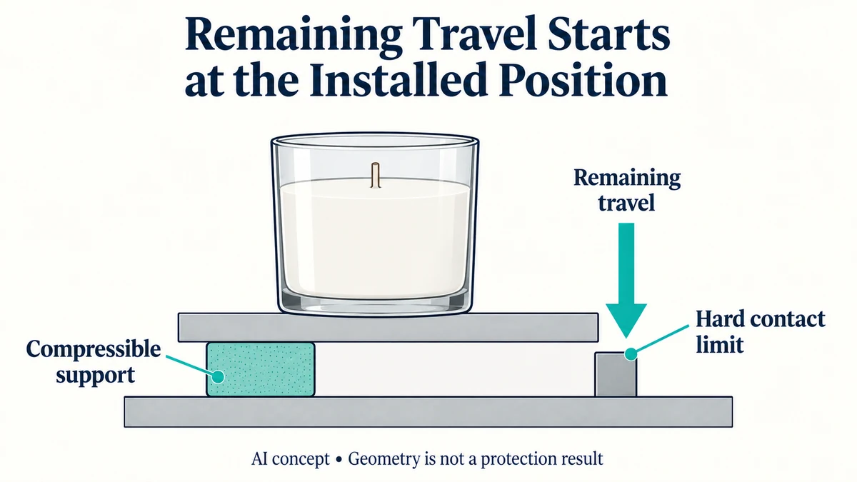
A soft pad cannot continue slowing a product through unlimited movement. Its installed condition leaves a finite distance before a rigid stop is reached or the material enters a different compression response. That remaining travel matters separately from how soft the loose pad feels.
A Contour-Cut PU Foam Beds Define the Product Contact and Compression Proposal is one physical configuration in which installed thickness and remaining movement need to be identified. Ask for the actual foam grade, contact area and loaded arrangement; the concept does not establish cushioning or compression performance.
For a glass candle pack, the useful question is how much movement remains available in the actual assembly and whether the cushion has relevant dynamic response over that movement. Bearing area or free foam thickness alone cannot supply the answer.
Free thickness is not the installed starting position
A pad can already be compressed by the product, closure or retaining arrangement before an impact occurs. The movement used to reach that starting state is no longer additional travel available from it.
The foam-deflection guide distinguishes a calculated installed compression state from a supplier’s reported material point. Remaining impact travel adds a different question: what can move from that installed state before another limit becomes relevant?
Identify the direction of that movement. A bottom pad’s vertical travel does not describe the jar’s side clearance. A restraint above the jar may also change which part moves and where a hard contact occurs.
The assembly must therefore show both its initial installed position and the limit under discussion. A loose-pad photograph shows neither relationship completely.
A simple hard-stop example locates the geometric limit
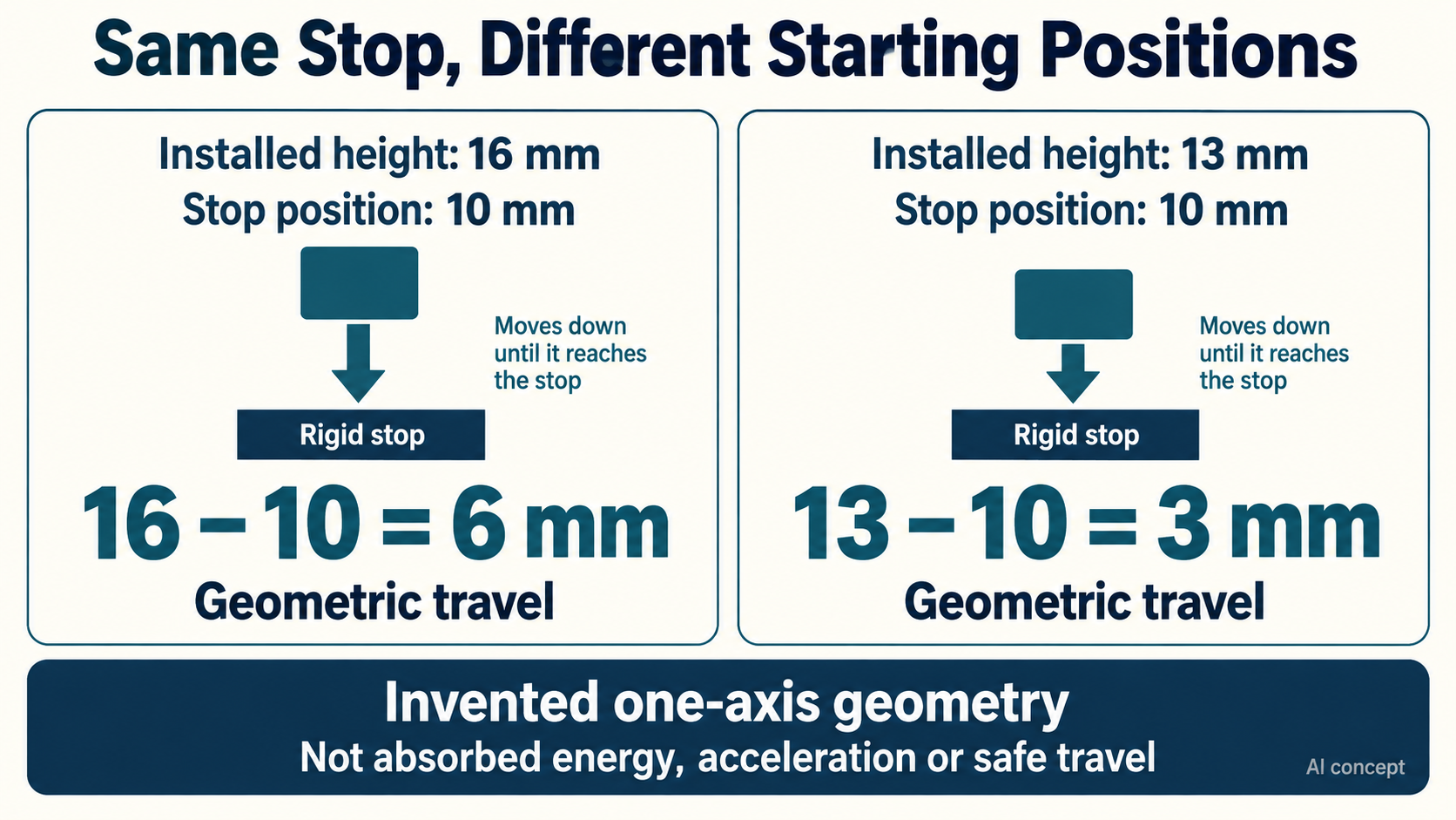
Consider an invented one-axis assembly in which a pad starts at an installed height of 16 mm. A separate rigid stop would contact when that supported height reaches 10 mm.
Under these idealized geometric assumptions, the additional travel to that stop is:
16 – 10 = 6 mm
Now consider an alternative installed state of 13 mm, with the same hypothetical 10 mm stop position. Its additional travel is:
13 – 10 = 3 mm
The second starting position leaves half as much geometric travel to that particular stop. This does not establish half as much absorbed energy, twice the transmitted acceleration or any protection outcome.
All dimensions are invented. The calculation assumes the identified parts move along the same axis and that the stop position stays fixed. It does not measure the foam’s useful compression range or show that either assembly can safely use every millimetre before contact.
If the pad becomes much harder to compress before the rigid stop is reached, the relevant material response may limit the useful travel earlier. If another part flexes or shifts, the simple geometric model may no longer describe the motion.
Bottoming out changes the response being relied on
During cushioning, the product’s motion and the support’s deformation are linked. As the available deformation is consumed, the support may no longer provide the response assumed at the beginning.
A rigid contact can add a new force path. A foam compressed into a much steeper response region can also resist further movement differently. Neither event needs to mean that all other packaging parts become perfectly rigid.
This is why “the pad is soft” is incomplete. Softness at one initial compression condition does not identify the force and motion throughout an impact.
The public scope of ASTM D1596-14(2023) describes dynamic shock cushioning characterization through acceleration-time data. It also states that material results need not equal package results and can depend on thickness and other test factors.
The catalogue supplies no approved stop position, compression percentage or impact-travel allowance for this candle pack. Relevant dynamic evidence belongs to the actual material and installed configuration.
More pad thickness can also change the starting constraint
Suppose the outer enclosure stays fixed while a thicker pad is proposed. That may increase free material thickness, but it can also raise the product, increase initial compression or change contact with the lid.
The new arrangement cannot inherit a larger travel allowance merely from the extra loose thickness. Its installed height, hard contacts and movement path must be resolved again.
Likewise, increasing bearing area changes a loading relationship but does not identify the distance before a stop. Area and travel are different inputs; neither alone establishes a suitable cushioning design.
Use the candle contact map to locate the product, support, lid and other contacts. Keep those interfaces with any relevant dynamic material data instead of treating the insert’s outer footprint as the whole protection system.
Compare the installed travel and the response over it
For a proposed support, identify its initial installed state, the relevant direction of movement and any rigid limit. Keep material-response limitations separate from the geometric travel calculation.
If the assembly permits motion but no relevant dynamic response is known, its protection remains unestablished. If a material curve exists but the installed pack reaches a different contact or compression limit, that curve cannot close the assembly question by itself.
Packrivo can coordinate the geometry and supplier evidence. The responsible technical reviewer must determine what installed response is acceptable for the product and impact conditions.
The practical comparison is between complete supported configurations with usable movement and relevant response, rather than between pads described only as softer or thicker.
Source scope: Checked 11 October 2026. ASTM’s official public catalogue identifies D1596-14(2023); the paid full procedure was not read. The 6 mm and 3 mm results are hypothetical geometry only, not measured cushioning stroke, absorbed energy, acceleration or safe product contact.
Recalculate travel when the stop moves
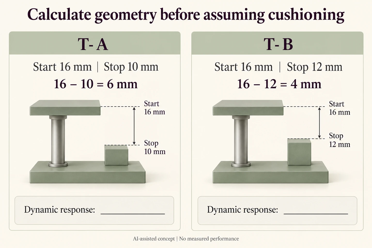
A changed stop can consume travel even when the installed starting height is unchanged. This additional invented one-axis comparison keeps the 16 mm starting reference and moves the stop from 10 to 12 mm. It describes geometry only.
Scroll horizontally if columns extend beyond the view.
| Case | Installed start | Stop reference | Geometric difference |
|---|---|---|---|
| T-A | 16 mm | 10 mm | 6 mm |
| T-B | 16 mm | 12 mm | 4 mm |
| Material response | Not provided | Not provided | Useful dynamic range remains unknown |
| Other contact | Separate component identity | Separate motion path | Reopen the model if it intervenes |
The subtraction is start minus stop on the same reference axis: 16 − 10 = 6 mm and 16 − 12 = 4 mm. T-B leaves 2 mm less geometric travel to this stop. The ratio 4/6 is not an energy, acceleration or protection ratio.
Keep the stop identity and reference plane with both measurements. A dimension to another surface, a flexible stop or another moving part may invalidate the assumed path. Do not silently clamp a negative difference to zero and call the assembly suitable; an inconsistent starting state needs review.
Neither value establishes that the cushion can use the full difference. Leave the dynamic-response and protection fields empty until evidence addresses the actual installed material, contacts and event. No impact, drop, compression percentage or acceptable stroke is prescribed.
Download the cushion bottoming out record (.csv). HYPOTHETICAL rows are invented examples. Use ACTUAL_BLANK for permitted project inputs; replace that row label only when recording actual facts. Empty evidence, observation and date fields mean unknown or not performed, never acceptance. Keep checkpoints and revisions separate.
Bring the installed start, stop identity and unresolved dynamic-response question through the existing enquiry route for the actual supported assembly. Packrivo coordinates independent suppliers. These records establish no supplier offer, service availability or MOQ exception; its published baseline is 500 pieces per product/design.