
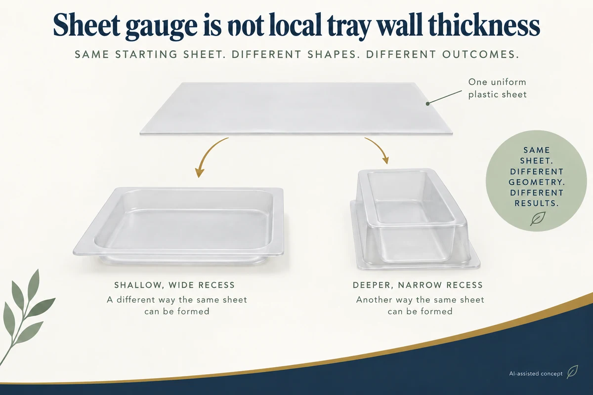
A thermoformed tray doesn't necessarily retain its starting sheet thickness at every finished location. Forming stretches the material into a new geometry, and local wall thickness can vary with the deformation and tool-contact history.
For a jewelry brand comparing insert designs, distinguish the nominal sheet gauge from the thickness distribution in the regions that perform the holding, contact and removal jobs. Matching sheet specifications don't establish identical formed trays.
Forming changes the surface the sheet must cover
A flat sheet becomes sidewalls, bases, corners and the areas between cavities. Different regions can participate in that deformation differently. A uniform starting sheet therefore doesn't guarantee uniform stretching throughout the finished part.
Formech's technical note on tool spacing and material stretching, published 5 October 2022, discusses how tooling arrangements affect material distribution. Its equipment-specific examples aren't thickness predictions for an unidentified PET jewelry insert.
Sheet gauge remains useful as a material input. It just doesn't describe every local wall after the forming operation. A supplier's starting-sheet number and a finished-tray measurement should keep their different identities.
Shape and contact can redistribute the deformation
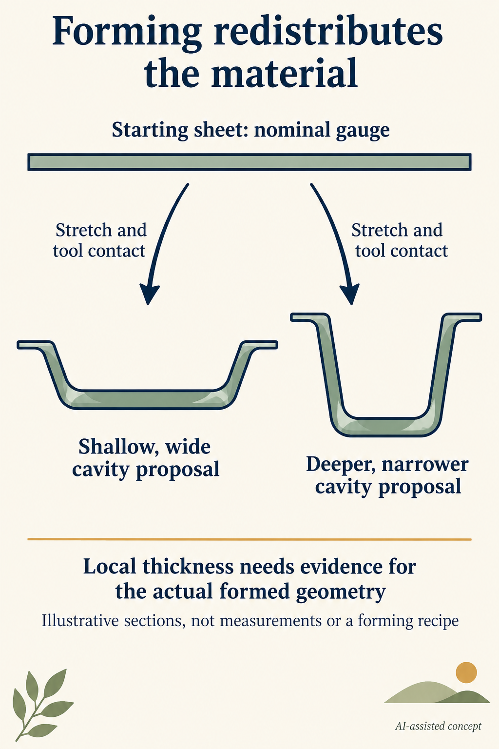
Cavity depth, opening width, corner geometry and neighbouring features can affect how the sheet stretches. Regions that contact the tool earlier may have a different subsequent deformation history from regions still being drawn into the shape.
Wagner and colleagues' original air-impact thermoforming study, published 23 March 2022, compares formed-wall measurements and modelling for a PVC cup configuration. It demonstrates a geometry-specific thickness distribution; its numerical results and local thin regions aren't transferred to gift inserts here.
The implication is a local-information question. The deepest point shouldn't automatically be declared the thinnest in every tray, and a specific paper's corner result shouldn't become a universal rule for all materials and tools.
A broad draw indicator doesn't identify every wall
A draw ratio can describe an overall geometric aspect of forming. It doesn't independently describe the local deformation everywhere or replace evidence for the actual finished geometry.
Two designs could have similar overall indicators yet different corner or cavity layouts. Conversely, a deeper recess changes the forming question without supplying a particular minimum thickness. Keep a broad descriptor distinct from a measured distribution.
No reduction percentage or sheet-to-wall conversion is calculated here. Such a prediction would require suitable information and a justified model for the actual material and process.
Follow two hypothetical jewelry insert proposals
Imagine two insert proposals made from the same nominal starting sheet gauge. One has a shallow, wide recess for a pendant card. The other has a deeper, narrower recess for a raised piece of jewelry. No trays have been measured for this teaching example.
Their sheet specifications match, but their formed surface requirements differ. The buyer can't assign the deeper candidate a minimum thickness or declare the shallower one mechanically superior from that distinction alone.
The buyer can instead identify which local regions matter to the intended function. A card-supporting base, an edge touched during removal and a retaining feature may need different construction information. A single overall gauge number leaves those locations unresolved.
A candidate change might retain the sheet while changing cavity geometry, or change the sheet while retaining the cavity. Those are different design directions. Keep the changed inputs identifiable before comparing the resulting formed parts.
Fit and local construction answer different questions
A tray may accommodate the jewelry's envelope while its local thickness remains unidentified. A fit observation doesn't provide a wall-thickness distribution, stiffness result or protection claim.
Packrivo's insert materials guide first distinguishes material forms and jobs. Its formed-tray edge guide locates contact and removal interfaces. Once thermoformed plastic is the candidate form, this article adds the material-distribution question within that geometry.
Request finished-geometry evidence for the regions relevant to the actual function, with the material and tray revision identified. Do not convert a starting-sheet specification into an assumed local minimum or a guaranteed protective outcome.
This explanation gives no forming temperature, pressure, equipment setting or Packrivo manufacturing capability. The useful decision is whether the selection can be supported by the original sheet specification alone, or needs the actual formed construction described and assessed.
Request a location-specific formed-wall record
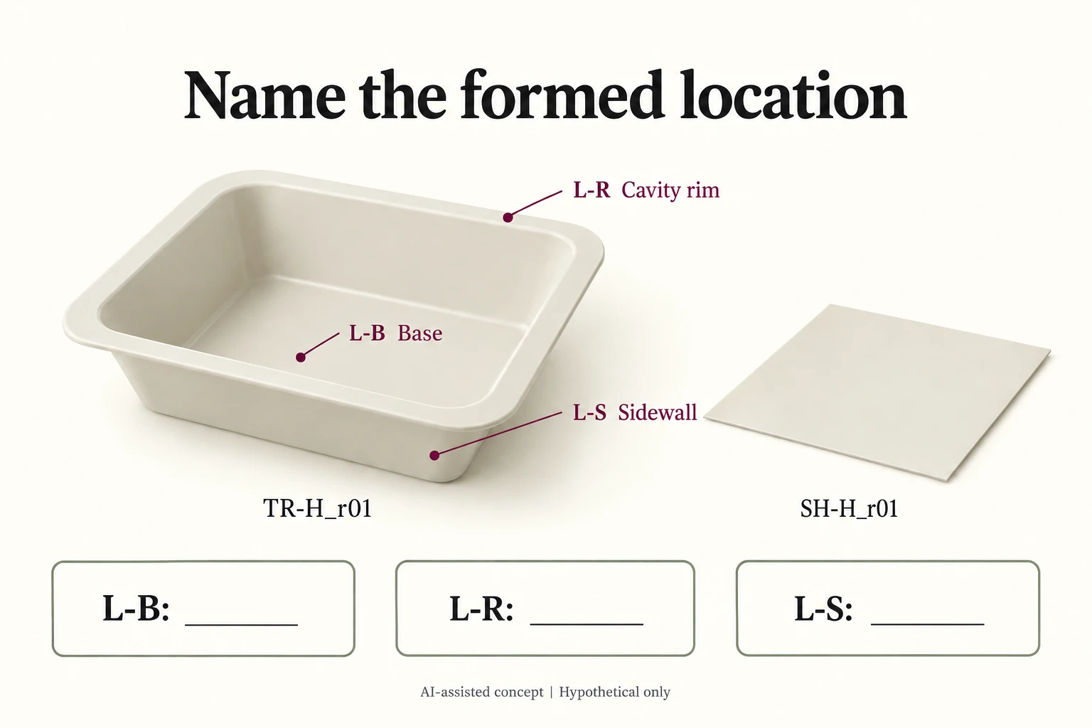
For new hypothetical tray TR-H_r01 made from sheet SH-H_r01, mark the card-supporting base L-B, cavity rim L-R and sidewall L-S. These locations are functional references, not presumed thin points.
Scroll horizontally if columns extend beyond the view.
| Location | Proposed job | Evidence request |
|---|---|---|
| L-B | Support the presentation card | Finished local construction for TR-H_r01 |
| L-R | Cavity rim near removal route | Local geometry and relevant wall information |
| L-S | Sidewall beside the held item | Finished location identity and information |
| SH-H_r01 | Starting sheet input | Keep nominal sheet information outside local-result cells |
Retain the same location names when comparing a revised cavity. If a location moves or no longer exists, describe that change explicitly; a measurement from another section must not silently inherit L-R.
A sheet gauge can be entered as an input once confirmed, but it cannot fill the three finished-location fields. The register deliberately leaves all thickness results empty. It contains no draw-ratio reduction estimate, universal minimum location or forming setting.
A supplier response should identify the formed tray revision, material and location behind the information. A substitute tray or different process remains a separate evidence scope. Fit, edge contact and protective function still need their relevant basis rather than approval from one local thickness figure.
Download the thermoformed tray wall thickness record (.csv). HYPOTHETICAL rows are invented examples. Use ACTUAL_BLANK for permitted project inputs; replace that row label only when recording actual facts. Empty evidence, observation and date fields mean unknown or not performed, never acceptance. Keep checkpoints and revisions separate.
Bring the exact tray and sheet revisions with the marked locations through the packaging enquiry before interpreting a nominal gauge as finished construction. Packrivo coordinates independent suppliers. These records establish no supplier offer, service availability or MOQ exception; its published baseline is 500 pieces per product/design.