
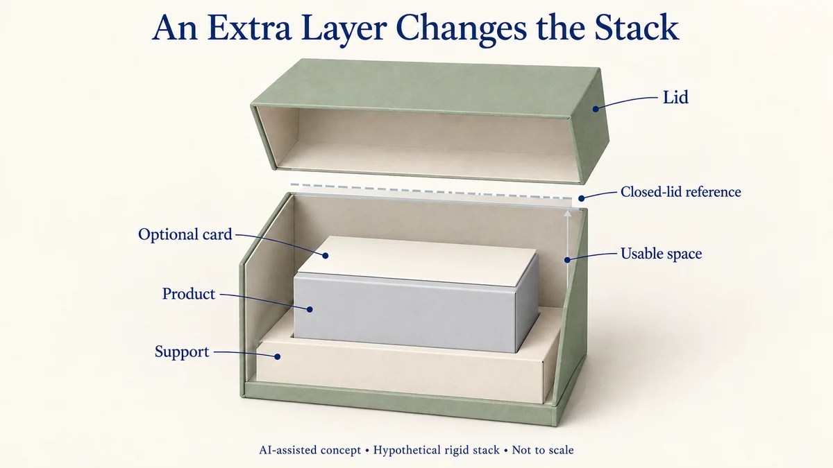
A gift box can have positive nominal lid clearance and still allow an interference combination when its components reach different ends of their permitted dimension ranges. Checking each component against its own limits is not the same as checking the space left in the complete assembly.
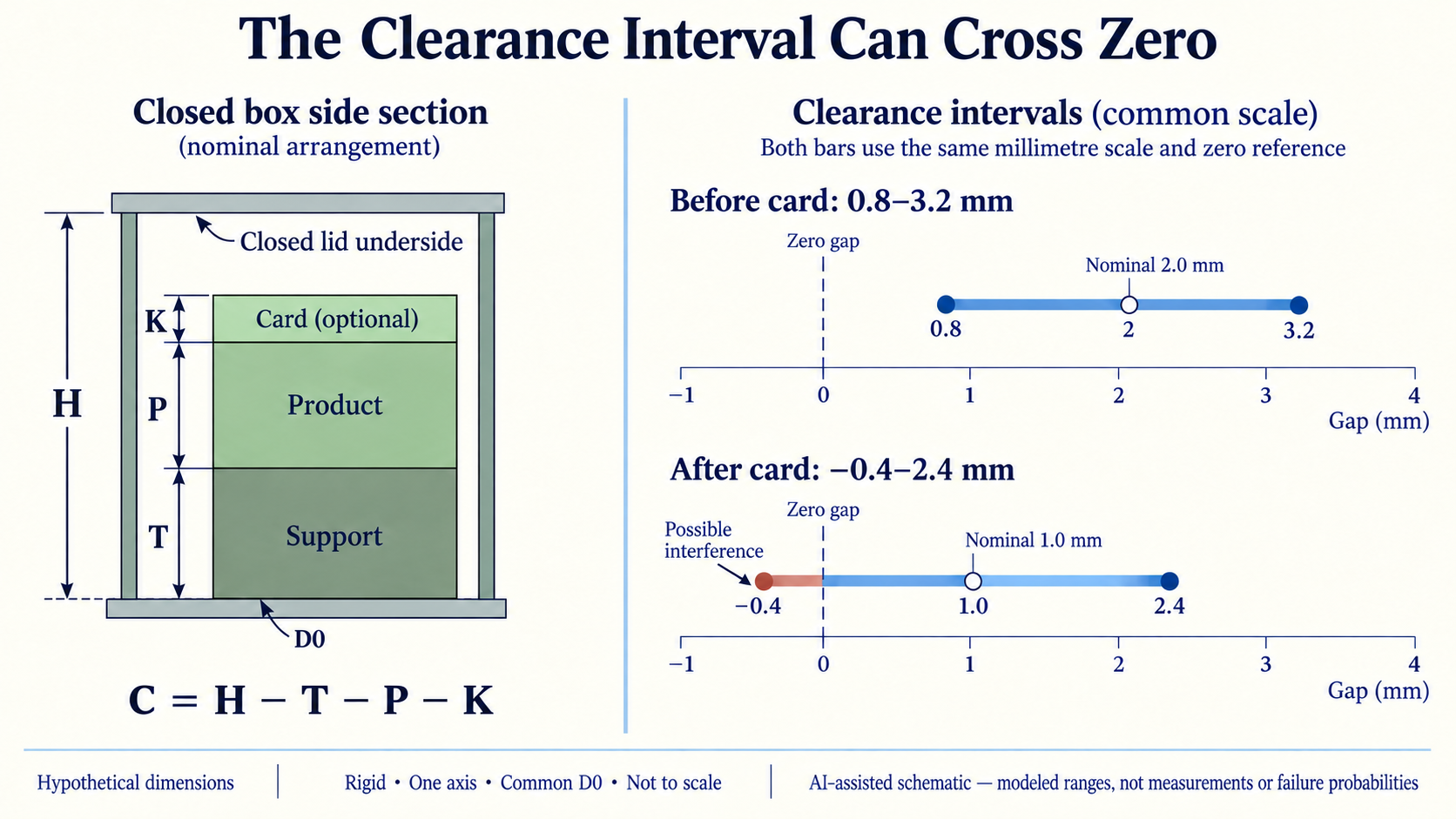
In a purely hypothetical rigid-box example, the nominal clearance above a product is 2.0 mm. Adding a 1.0 mm information card reduces nominal clearance to 1.0 mm. But the more important change is in the calculated range: the minimum possible gap moves from +0.8 mm to −0.4 mm.
That negative endpoint means the specified component ranges permit a combination that cannot fit within the assumed rigid, closed-lid geometry without interference. It is not an observed packaging defect or an estimate of how often interference will occur.
Define the vertical dimensions before combining them
Consider a shallow gift box holding a rigid product on a seated support. The lid closes above the product, and a card may be placed directly over its highest point.
Use four dimensions:
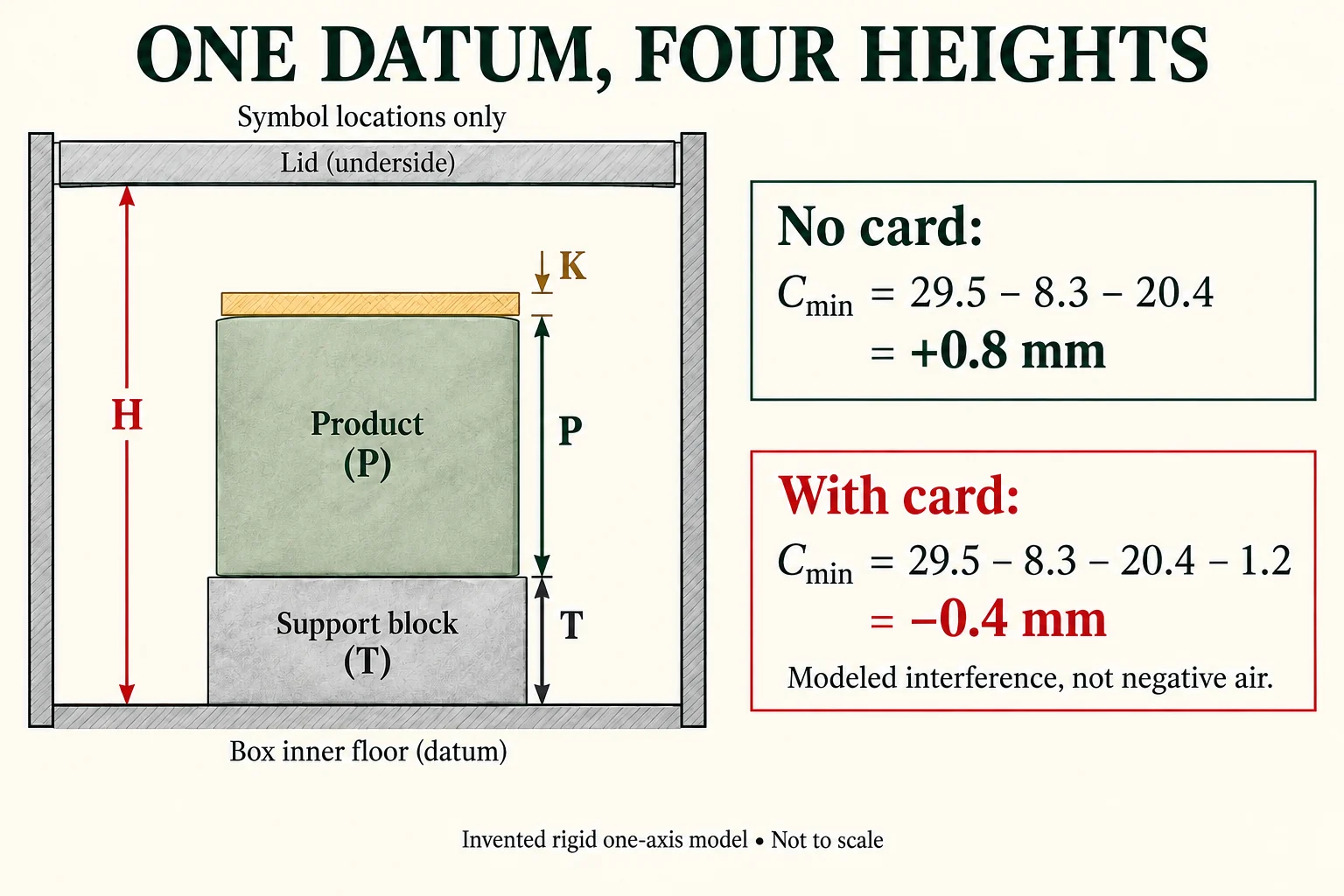
- H — usable closed-lid height: the vertical distance from the finished inside-base reference plane to the underside of the lid in its specified fully closed position.
- T — seated support height: the distance from that same base reference plane to the surface supporting the product.
- P — product height: the vertical distance from the support surface to the product’s highest packed point.
- K — added card-layer thickness: the height occupied by the card directly above that point, when this placement is used.
These quantities must describe the same assembled configuration. H is not the box’s advertised external height, and T is not necessarily the loose thickness of an uninstalled insert.
The example assumes one vertical measurement direction, a common base datum, additive heights, rigid noncompressible components, and no changes in orientation or seating during closure. It also treats the stated dimension limits as combinations that are not otherwise restricted by the design.
Those assumptions are essential. They allow the remaining vertical gap to be expressed as:
C = H − T − P
When the card occupies the same vertical stack:
C = H − T − P − K
A positive C represents a modeled gap. Zero represents nominal geometric contact under this model. A negative C represents an overlap that the assumed rigid components cannot accommodate without changing the geometry.
The general idea is dimensional fit between components. KEYENCE’s What is Fit?, an undated measurement education page accessed on 10 October 2026, explains clearance and interference using mating shaft-and-bore features. That example supports the distinction between clearance and interference, but it does not prescribe dimensions or tolerances for gift boxes.
Calculate the gap across the original component ranges
All numbers below are invented solely for this hypothetical teaching example. They are not Packrivo measurements, supplier specifications, recommended packaging tolerances, or customer results.
| Dimension | Minimum | Nominal | Maximum |
|---|---|---|---|
| Usable lid height H, 30.0 ± 0.5 mm | 29.5 | 30.0 | 30.5 |
| Seated support T, 8.0 ± 0.3 mm | 7.7 | 8.0 | 8.3 |
| Product height P, 20.0 ± 0.4 mm | 19.6 | 20.0 | 20.4 |
| Optional card K, 1.0 ± 0.2 mm | 0.8 | 1.0 | 1.2 |
All table values are in millimetres.
Without the card, calculate the nominal gap first:
C nominal = 30.0 − 8.0 − 20.0 = 2.0 mm
Next calculate the smallest remaining gap. This occurs when usable lid height is at its minimum while the occupied support and product heights are at their maxima:
C minimum = 29.5 − 8.3 − 20.4 = 0.8 mm
The largest modeled gap comes from the opposite combination:
C maximum = 30.5 − 7.7 − 19.6 = 3.2 mm
The resulting interval is:
Without card: 0.8–3.2 mm
Under the stated additive and rigid assumptions, every combination within these dimension ranges leaves a positive vertical gap at this particular interface.
That does not establish a suitable clearance for the product. It only establishes that the modeled vertical stack does not cross zero within the specified intervals.
The distinction between an assembly result and an individual dimension is central to NIST IR 6223, Design for Tolerance of Electro-Mechanical Assemblies: An Integrated Approach, published in September 1998. Its introduction and Section 4.1 distinguish worst-case analysis, which examines extreme component combinations, from statistical analysis using distribution information.
The NIST report concerns electro-mechanical assemblies, not packaging. This article applies the elementary high-low interval principle to an explicitly hypothetical packaging geometry; it does not adopt the report as a current packaging standard.
The added card makes the gap interval cross zero
Now place a card layer directly above the product’s highest point.
Its hypothetical nominal thickness is 1.0 mm, with a permitted range of 0.8–1.2 mm.
The nominal calculation becomes:
C nominal = 30.0 − 8.0 − 20.0 − 1.0 = 1.0 mm
A nominal-only review might conclude that the card still fits because the result is positive.
But the smallest gap must account for the thickest permitted card together with the other limiting dimensions:
C minimum = 29.5 − 8.3 − 20.4 − 1.2 = −0.4 mm
The largest remaining gap is:
C maximum = 30.5 − 7.7 − 19.6 − 0.8 = 2.4 mm
The new interval is:
With card: −0.4–2.4 mm
The minimum combination occupies 29.9 mm of the available 29.5 mm. The modeled shortfall is therefore 0.4 mm.
| Calculated state | Without card | With card |
|---|---|---|
| Minimum gap | +0.8 mm | −0.4 mm |
| Nominal gap | +2.0 mm | +1.0 mm |
| Maximum gap | +3.2 mm | +2.4 mm |
The card does more than subtract its nominal thickness. Its own dimensional range extends the spread of possible assembly clearances.
Every input in the minimum-gap calculation remains inside its individual hypothetical limits. Yet the combined dimensions exceed the usable height of the closed box.
This is the reason a component-by-component dimensional acceptance review cannot answer the complete fit question on its own.
A negative modeled gap does not mean a real package has negative air space. It means the idealized closed geometry contains incompatible occupied and available dimensions. An actual component might bend, compress, shift, prevent full closure, or contact another surface. Which behavior occurs cannot be determined from these intervals.
Nor does the interval indicate a failure percentage. It shows an extreme combination permitted by the assumed inputs, not how often those endpoints coincide. The calculation supplies no manufacturing distributions, correlations, sampling evidence or statistical yield estimate.
Identify which dimension or interface must change
Once the modeled minimum gap crosses zero, the design question becomes more specific than whether the nominal box height looks sufficient.
The relevant minimum-gap relationship is:
C minimum = H minimum − T maximum − P maximum − K maximum
This expression identifies four possible contributors, but it does not decide which component should be changed.
The responsible designer might consider increasing usable closed-lid height, revising the seated support, changing the product’s packed position, or moving the card outside the vertical path above the product.
Each choice changes a different physical interface.
Increasing the advertised exterior height does not necessarily increase H by the same amount. The lid, wrap, lining and closed position must still be considered.
Reducing the loose thickness of an insert does not necessarily reduce its installed support height T. The relevant dimension is its position when seated.
Changing product orientation may change its highest packed point, but it also changes the geometry being analyzed. An angled product cannot automatically retain the same additive model.
Moving the card into a separate pocket might remove K from the stack above the product. It creates another placement question rather than proving that the revised arrangement fits.
The calculated 0.4 mm shortfall is the amount by which this particular worst-case combination exceeds zero clearance. It is not a recommended design increase. Zero clearance itself may be unacceptable for the product or package.
The design needs an agreed functional clearance requirement. The responsible party can then compare that requirement with the minimum predicted gap for the actual construction.
For the underlying measurement definitions, Packrivo’s dimensions and acceptance-method guide explains how to specify reference points and measurement conditions. Its care-card pack-out guide addresses placement and loading order. This calculation answers a narrower question that those workflows leave open: what range of resulting clearance follows from the combined component ranges?
Keep the interval attached to the actual construction
A worst-case arithmetic model is useful only when its dimensions represent the same physical arrangement.
Consider a foam holder that compresses under the product. Its installed support height may depend on loading, and the original rigid T range may no longer describe the assembly.
A hinged box can also have local clearance controlled by lid rotation, rather than a single vertical distance. A tilted jar, raised jewellery setting, turned paper edge or incompletely seated insert may introduce contact outside the section used for the calculation.
Another limit arises when the component extremes cannot physically occur together because their dimensions are linked. In that case, independently combining every interval endpoint can overstate the feasible range. The actual relationships need to be established before replacing the simple model.
An installed section should therefore identify where each quantity begins and ends, which finished surfaces it includes, and whether the complete construction permits the assumed additive relationship.
For formed lid and base interfaces, the separate Packrivo article on folded wall builds addresses the construction details that a simple height equation does not capture.
The interval also says nothing about whether a product is adequately retained, easily removed, protected from rubbing, or suitable for transport. Even a strictly positive calculated gap cannot certify those outcomes. Representative physical review and any agreed performance evaluations remain separate decisions.
Keep the clearance calculation attached to named interfaces
Use the same base datum in the drawing and worksheet. H and T start at that plane; P starts at the installed support surface; K belongs only when the card lies above the product in the analyzed path. A separate card pocket cannot inherit the same K subtraction without locating its geometry.
For the existing hypothetical dimensions, the worksheet retains all four min/nominal/max inputs and both resulting clearance rows. Before using the arithmetic for a real design, the responsible designer should state whether compression, a tilted product, linked component limits or local lid rotation invalidate the rigid additive assumptions. Leave the required functional gap open until that requirement is agreed; neither zero nor 0.4 mmis a design recommendation.
Download this article’s project record (CSV). The record includes field definitions, labeled teaching examples and a blank project row. Add source evidence and the details of your actual project.
For a sourcing discussion, send the shared-datum section, four component ranges and the functional gap still to agree. Packrivo coordinates supplier questions; the responsible technical or commercial parties confirm the actual method, configuration and terms.
Use the calculation to request a specific design response
Return to the hypothetical card addition.
Before the card, the modeled clearance remains between 0.8 and 3.2 mm. After the card, the modeled interval becomes −0.4 to 2.4 mm. The negative minimum flags a design combination that the stated rigid stack cannot accommodate.
The next useful question is:
Does the card really occupy the same vertical stack as the product’s highest point? If it does, which finished dimension, seating position or card interface will the designer revisit so the minimum modeled clearance meets the project’s actual requirement?
The answer should identify the construction to be reviewed, not simply supply another nominal box size.
Packrivo can help coordinate that question with the relevant packaging proposal, drawings and supplier response. The arithmetic helps buyers locate a potential dimensional conflict; it does not substitute for the designer’s geometry assessment, a representative finished sample, or functional testing.
The decision is straightforward: evaluate the remaining clearance interval, not only the nominal gap, and revisit the interface when the permitted combination conflicts with the required space.
Sources checked 10 October 2026. NIST IR 6223 was published in September 1998 and concerns electro-mechanical assemblies; KEYENCE’s measurement-education page shows no confirmed publication date. The elementary interval calculation is applied here to the stated hypothetical rigid packaging stack, not as a packaging standard, a physical fit result or a statistical yield estimate.