
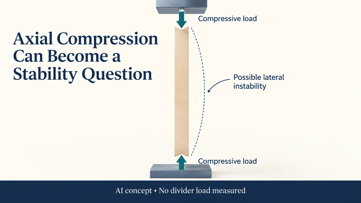
A slender divider can become unstable under an axial compressive load before the material reaches its crushing limit. The structure’s height, support and end constraints matter alongside the board itself.
The Paperboard Grid Divider: Match Grid Slots to Each Retail Item provides a reference for locating divider spans, slots and supported edges. Confirm the actual board direction and installed supports before interpreting a buckling proposal; the concept gives no load rating.
For a gift pack, this creates a different purchasing question from whether a sheet is stiff when bent or whether corrugated board has a stated edge-crush value. Ask how the particular divider is loaded and restrained in the complete assembly before carrying a material result into a structural claim.
Identify whether compression actually reaches the divider
A divider separating two products is not automatically a load-bearing column. It might simply locate the items laterally. If a lid, upper tray or stacked component transfers a vertical load into it, the proposed role changes.
Locate the contact above and below the member. An axial compression model requires an actual load path along the member, not a downward arrow placed near a photograph.
If the load is eccentric or the divider is already curved, bending can accompany compression. If the member lacks contact at one end, the assumed axial path may not exist. Those conditions belong in the technical review of the configuration.
This guide supplies no load for an actual divider. It explains why identifying its role comes before discussing stability.
Buckling concerns loss of a stable shape
Material crushing concerns the material response under compression. Buckling concerns an initially supported structure becoming unstable and moving sideways under compression. The two mechanisms need not begin at the same load.
MIT’s public lecture on elastic instability explains ideal column behaviour and shows how bending stiffness, length and end conditions affect critical load. It also describes instability below material yield in appropriate slender-column cases.
Those ideal relationships explain a mechanism. They are not a safe-load calculator for folded paperboard. A real divider can have folds, slots, joints, anisotropic material response and imperfections absent from the simple column model.
The responsible technical reviewer must determine which model or evaluation is relevant to the actual member. A board’s marketing description cannot supply those missing structural conditions.
Unsupported length is different from outside height
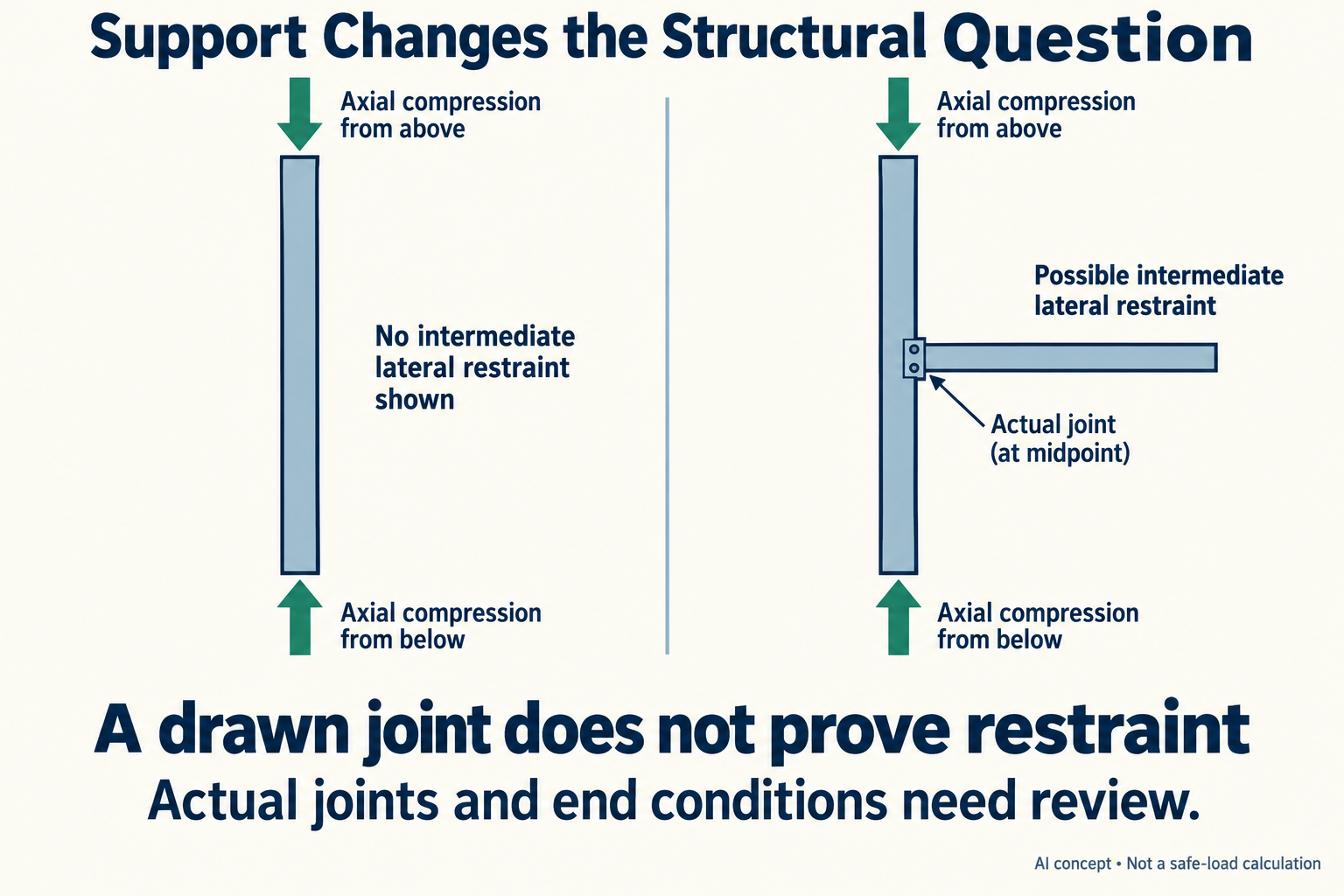
Imagine an invented tall divider reaching from a tray base to an upper component. In one proposal, it has no intermediate lateral engagement. In another, a located crossing divider provides possible lateral restraint midway up its height.
The outside height can remain the same while the supported arrangement changes. That difference can matter to lateral instability if the crossing part genuinely restrains the relevant motion.
A drawn intersection is insufficient evidence of restraint. A loose slot, flexible neighbour or connection that permits sideways movement may not provide the support assumed in a simplified model. Contact in one direction may also leave another direction less restrained.
Do not assign a critical-load ratio to these two proposals. Their actual stiffness, joint behaviour and end conditions have not been established. The useful output is a located question about what the crossing connection restrains.
A board figure describes a different object
The edge-crush and box-compression comparison separates board-specimen evidence from assembled-container evidence. A tall divider introduces another object and another structural condition.
A corrugated board result does not directly establish the buckling load of a cut and slotted divider. Likewise, a compression result for a complete carton does not automatically isolate the divider’s role inside it.
Sheet bending evidence can be useful input, but it still needs the relevant material direction and structural geometry. Turning a cutting layout or changing the slot can alter the configuration even if the supplier keeps the same board grade.
Keep material evidence with its actual direction and scope. Then ask what additional evidence addresses the proposed loaded member.
Examine supports before prescribing thicker material
Suppose a designer responds to an instability concern by proposing thicker board. That may change stiffness, but it can also change slot fit, fold behaviour and the way contacts engage. The assembled support should be reviewed again.
A different proposal might add a lateral connection or change unsupported length. That changes the structural question without necessarily changing the nominal material grade. Neither proposal is proven superior by this hypothetical comparison.
The glass contact map can help locate the interfaces in a candle pack. Extend that map to show which components carry axial load and which are intended to restrain lateral motion.
Ask the supplier and technical reviewer to distinguish intended support from assumed support. A clear drawing of contacts and joints makes that discussion more useful than an isolated request for a stronger divider.
Packrivo can coordinate the configuration and material information. It does not establish an allowable divider load from an ideal lecture model or a board label.
Source scope: Checked 11 October 2026. MIT’s Mechanics and Materials II Lecture 2 is dated 9 February 2004. Its public explanation concerns ideal elastic instability, not paperboard packaging approval. No divider, load, joint, stiffness or critical force was tested here. All proposed support comparisons are hypothetical.
Establish the load path before naming unsupported length
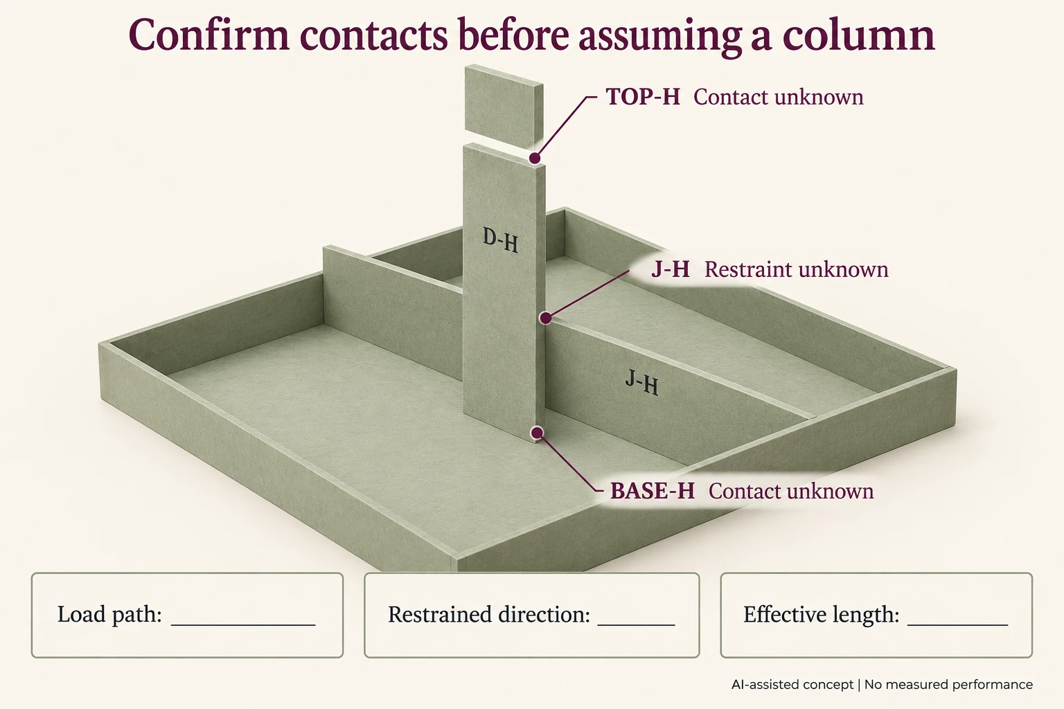
A divider drawing needs two different confirmations: whether axial load reaches the member, and whether a crossing connection restrains lateral movement. The invented member D-H below has no assigned load or critical-force calculation.
Scroll horizontally if columns extend beyond the view.
| Reference | Proposed relationship | Confirmation required |
|---|---|---|
| TOP-H | Upper component meeting divider end | Actual contact and axial-load route |
| BASE-H | Divider end meeting lower support | Actual lower contact and constraint |
| J-H | Crossing divider at named location | Which lateral motion it restrains, if any |
| J2-H revision | Changed slot or neighbour | Reassess engagement rather than assume bracing |
Do not assign an effective length from a drawn crossing alone. First identify the connected parts, slot fit and permitted movement in each relevant direction. A contact that restrains one direction can leave another unresolved.
If TOP-H does not transfer axial load, the intended column model may not describe this member’s role. If the load is offset, retain that geometry for technical review instead of putting a centred compression arrow on the drawing.
A thickness revision can change both stiffness and slot engagement. Preserve those as separate changed inputs. This record supplies no Euler load, factor-of-four support ratio, allowable capacity or buckling result for real paperboard.
Download the paperboard divider buckling record (.csv). HYPOTHETICAL rows are invented examples. Use ACTUAL_BLANK for permitted project inputs; replace that row label only when recording actual facts. Empty evidence, observation and date fields mean unknown or not performed, never acceptance. Keep checkpoints and revisions separate.
Bring the end-contact and crossing-joint questions through the original enquiry route before describing the divider as load-bearing or braced. Packrivo coordinates independent suppliers. These records establish no supplier offer, service availability or MOQ exception; its published baseline is 500 pieces per product/design.