
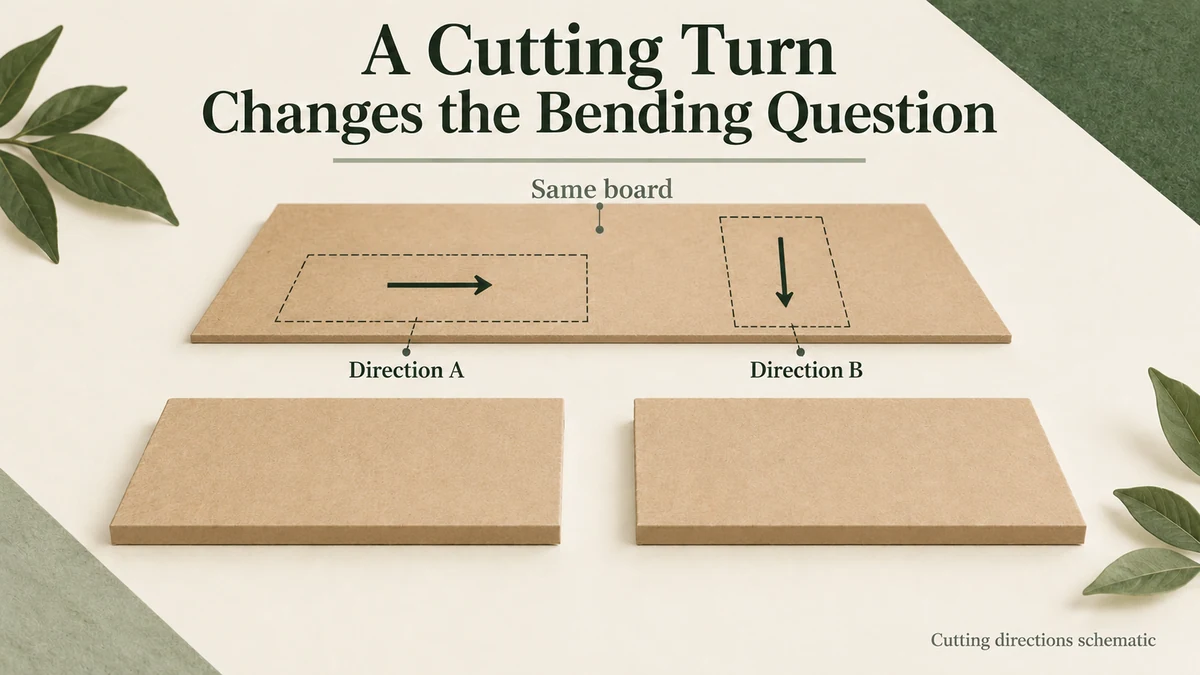
Rotating a corrugated divider on the cutting sheet can change its bending response even when the board grade, thickness and weight stay the same. The important relationship is between the board’s structure and the direction in which the finished piece spans, bends and carries load.
For a candle or gift brand, this matters when a converter proposes a different cutting layout. A material name alone cannot establish that the revised divider will behave like the earlier one.
The board contains more than one structural direction
Corrugated board combines facing sheets with a shaped internal layer. Its construction has directions, rather than the same arrangement along every line through the sheet. The component papers also have their own directional properties.
When a panel bends, one face tends to extend while the opposite face tends to shorten. The connected layers participate in that deformation. Turning the board relative to the span changes how its directional construction is used.
TAPPI’s public description of T 836 om-25 specifically distinguishes machine-direction and cross-direction bending stiffness of corrugated board using four-point loading. Its description retains direction as part of the measurement basis.
The catalogue does not establish which direction is preferable for an unspecified divider. It also does not make a supplier’s result from one direction applicable to the other.
Keep the supplier’s board-axis reference separate from a drawing’s page orientation. A long sheet edge, a box’s longest wall and a visible flute line are not interchangeable names for the direction used in a report. The supplied construction and axis convention need to be identifiable.
The span and the bending axis are different references
A divider supported at two ends has a span between those supports. A force acting across that span can make it bow. The line about which a section bends is a different geometric reference from the span itself.
This can make an instruction such as “put the strong direction across the box” ambiguous. Across which dimension, between which supports, and for which applied load?
Identify the intended supports and the direction of bending first. Then relate that arrangement to the confirmed board axes. If the divider instead receives a force along its height, a separate compression or stability question may arise. An out-of-plane bending comparison cannot settle every loading mode.
The grain and crease map helps preserve a sourced material direction at a fold. Here the additional question is how a corrugated piece uses its direction while spanning and bending between supports.
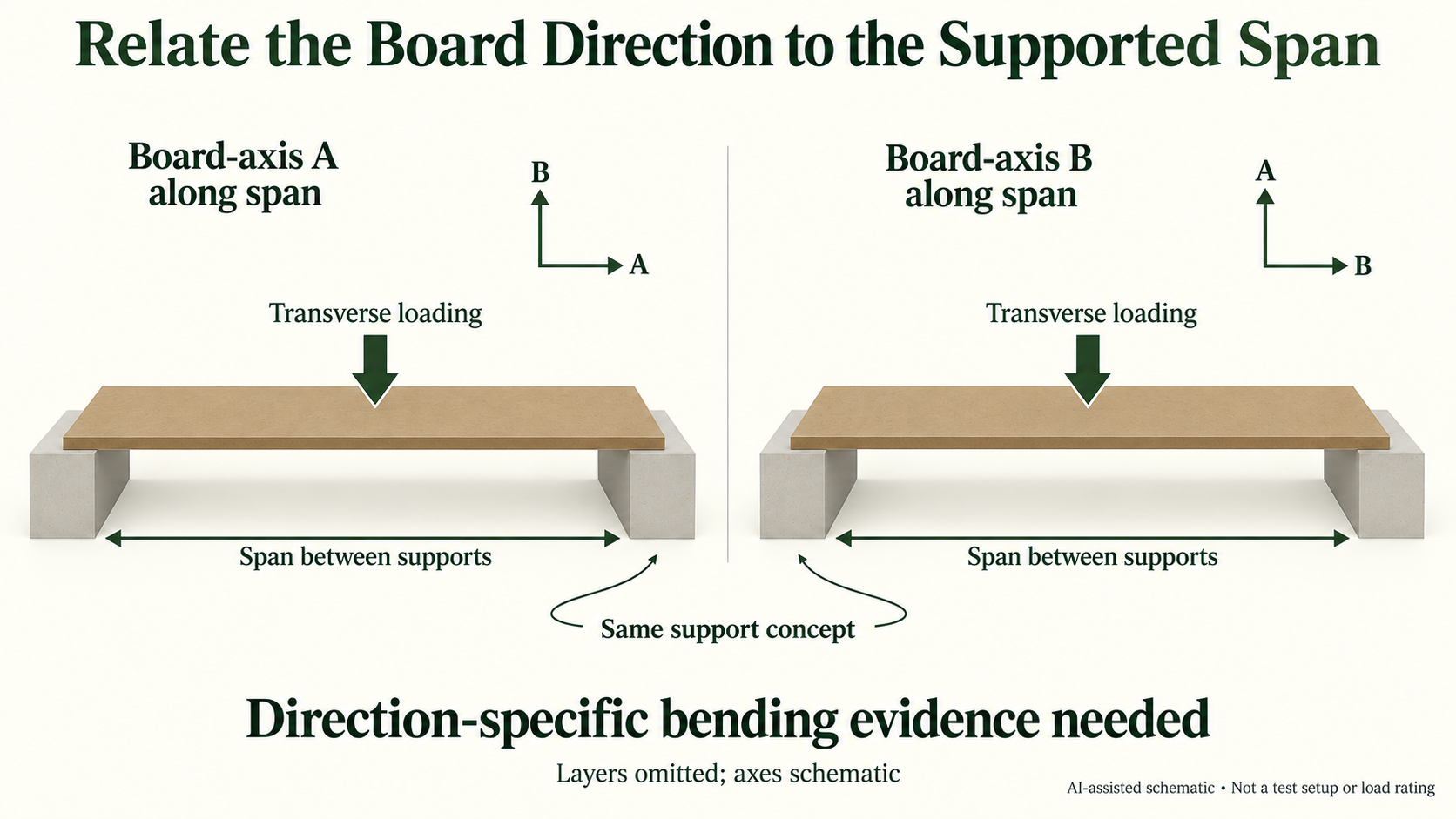
Compare two cuts from one hypothetical sheet
Consider a hypothetical candle pack with a removable corrugated divider. Both proposed pieces have the same outline and are intended to fit the same slots. One is cut with its long span in board direction A; the other is cut after rotating the outline by 90 degrees on that same sheet.
The letters A and B are explanatory labels, not assumed machine-direction or flute-direction measurements. No divider has been made or loaded for this example.
The two pieces can share the same nominal thickness and grammage while using different board directions along their span. If they are compared under the same support and loading arrangement, the direction change remains a meaningful variable.
However, a revised slot, crease, cutout or end support would change the comparison too. A piece held firmly at its ends is not equivalent to one that can rotate or slip there. Calling both pieces the same divider does not remove those construction differences.
The useful outcome is an identified direction-and-support comparison. There is no measured stiffness ratio, preferred orientation or load rating to infer from this hypothetical drawing.
Directional stiffness does not approve the whole insert
Bending stiffness describes resistance to a particular deformation under a stated basis. It does not independently establish rupture resistance, edge-crush strength, repeated movement or protection of the packed candle.
Nor can the corrugated section automatically be replaced by a solid rectangle whose thickness equals the board’s outside caliper. Its connected faces and shaped internal layer are part of the construction.
Packrivo’s grammage and caliper guide separates mass per area from thickness. A direction-specific bending question adds information that neither of those material descriptions supplies.
For a proposed layout change, preserve the actual board identity, marked axes, divider outline and supported span. Ask the responsible converter or technical reviewer which directional evidence relates to that arrangement. A result for a flat specimen remains specimen evidence; the finished slotted or folded divider needs its own relevant review.
The decision is whether the new cutting orientation is supported for the divider’s intended bending job. Packrivo can coordinate that question with the drawing and material proposal, without claiming a bending test or certified insert capacity.
Source scope: Checked 11 October 2026. TAPPI’s official indexed catalogue describes T 836 om-25 and its machine/cross-direction four-point scope; direct tool access to the catalogue was restricted. The paid full method was not read. No material direction, divider response or packaging performance was measured for the example.
Separate a cutting turn from a support revision
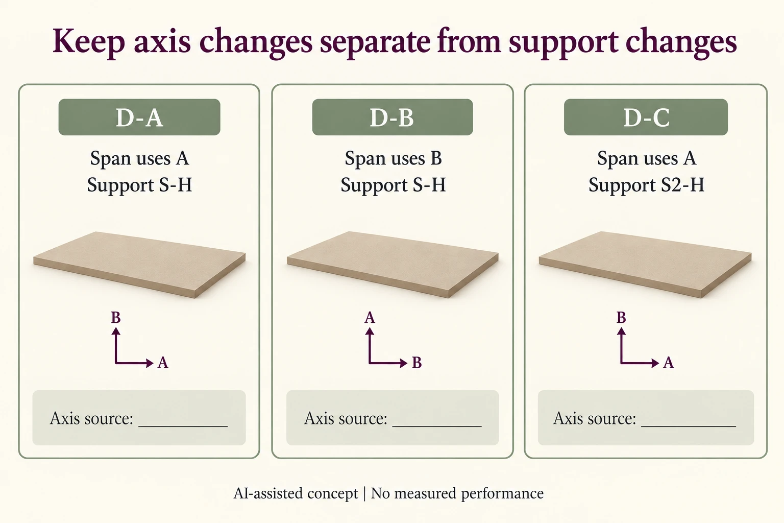
The invented divider family below keeps the outline and board reference fixed while separating two revisions. A and B are placeholder board-axis names, not confirmed machine, cross or flute directions.
Scroll horizontally if columns extend beyond the view.
| Proposal | Span relationship | Support reference | Decision still needed |
|---|---|---|---|
| D-A | Span along A | S-H | Source the axis convention and relevant evidence |
| D-B | Span along B | S-H | Review the axis change with the same support |
| D-C | Span along A | S2-H | Review the support change independently |
| D-A plus new slot | Axis unchanged | Support effect unconfirmed | Do not inherit the earlier boundary condition |
Use a sourced axis key beside the finished divider drawing. A page rotation can leave the physical relationship unchanged; a cutting rotation relative to the supplied sheet can change it. Record which of those occurred instead of describing both as rotating the drawing.
The support reference should identify where the piece engages, whether the ends can rotate or slip, and the relevant span. D-C deliberately changes that reference. Comparing D-A with a version that changes both axis and slot cannot isolate a directional contribution.
Leave stiffness values and a preferred orientation empty. These rows select the next comparison, not the winning cut. A material result needs the matching axis convention and method; a cut and slotted divider still needs evidence for its actual role.
Download the corrugated board flute direction stiffness record (.csv). HYPOTHETICAL rows are invented examples. Use ACTUAL_BLANK for permitted project inputs; replace that row label only when recording actual facts. Empty evidence, observation and date fields mean unknown or not performed, never acceptance. Keep checkpoints and revisions separate.
Bring the sourced axis key, outline and support revision through the enquiry route already linked above before confirming a cutting-layout change. Packrivo coordinates independent suppliers. These records establish no supplier offer, service availability or MOQ exception; its published baseline is 500 pieces per product/design.