
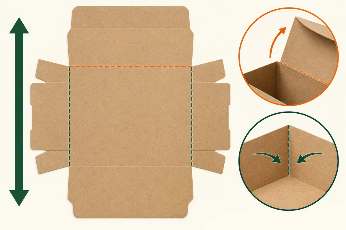
Map the proposed board’s machine direction onto the dieline, then identify each important crease as parallel or perpendicular to it. Keep panel names and crease IDs fixed through revisions. Ask the converter to review the map with the selected board and tooling before treating a fold layout as approved.
A note that says ‘check grain’ is hard to act on. A panel map with a confirmed direction arrow lets the material supplier, structural designer and buyer discuss the same crease instead of each interpreting the note differently.
Obtain a confirmed grain reference
Holmen’s technical information distinguishes machine direction from cross-machine direction and explains long-grain and short-grain sheet descriptions. Use the confirmed reference for the supplied sheet or proposed layout. The longest dimension of an assembled box is not enough to establish it.
Ask the responsible source to mark the direction on the material or cutting layout. Save that reply with its date and grade. If your team adds the arrow to a working drawing, record where the information came from.
Keep the drawing upright in a stated orientation, such as the main print face reading normally. An arrow copied onto a rotated page without its orientation can create a new ambiguity.
The folding box specification guide covers the wider brief. This method creates a specific map for one material and dieline revision.
Name the panels and folds before comparing directions
Give each important crease a stable ID, such as C1 for the lid hinge and C2 for the front-wall fold. Add panel names that describe the formed box, not just their position on the page.
Place one confirmed machine-direction arrow on the map. Record whether each crease line runs parallel or perpendicular to that arrow. If the geometry or direction remains unclear, write ‘unconfirmed’ rather than inferring the answer from a product photograph.
Holmen’s creasing guidance explains that creasing geometry and operation must match the paperboard. The machine/cross-machine direction terms come from the separately linked technical PDF, while this chapter supports a converter review of the chosen board and tool. It doesn’t give a universal buyer rule that one grain layout solves every carton.
Use a panel and crease-direction record
Copy these fields into a drawing note or spreadsheet. Keep the grain source and the crease observations separate.
| Crease ID | Formed panels joined | Direction relative to MD | Review action |
|---|---|---|---|
| C1 | Named lid and rear wall | Parallel, perpendicular or unconfirmed | Converter response and sample photo |
| C2 | Named base and front wall | Parallel, perpendicular or unconfirmed | Formed angle and visible surface record |
| C3 | Named side and corner panel | Parallel, perpendicular or unconfirmed | Setup action and corner result |
| Material reference | Grade and sheet layout | Arrow source and date | Confirm before comparing revisions |
| Revision link | Dieline and sample IDs | Direction changed or retained | List folds needing another review |
The rows are prompts, not a claim that these crease directions have been tested. Replace the example panel names with the parts on your proposal.
Follow a hypothetical hinged-lid carton change
Suppose a gift brand rotates a dieline on a sheet to discuss a revised layout. Its lid hinge still has the same name, but the proposed material direction on the cutting plan changes. The buyer keeps C1 as the lid-hinge ID and updates the direction column.
That small record tells the converter which fold question has changed. The team requests a formed sample on the new proposal instead of carrying forward approval from an earlier arrangement.
For a prepared four-corner carton, some folds appear during base setup and another controls the attached lid. The map should identify those actions separately. A general note about box folding would leave both questions blended together.
Photograph the crease flat and after the intended forming action. Record the board and print used. Keep observations factual, such as a visible line along C1, without diagnosing the cause from a photograph alone.
Carry the grain map through a layout change
Give the hypothetical lid hinge the stable name C1 even when the dieline moves or rotates on a sheet. Keep the sheet direction arrow sourced from the material or converter reply. A new position on the page shouldn’t cause C1 to become a different fold simply because the designer renumbered everything.
For the revised proposal, record three entries: the old direction relationship, the proposed new relationship and the supplier response. If the arrow itself is unconfirmed, keep both relationships provisional. A confident-looking sketch cannot resolve a missing grain reference.
Ask the converter: ‘Does the C1 review need to change under the new sheet layout and named board?’ That question gives the responsible source the fold and material context. It doesn’t ask the buyer to prescribe a creasing rule or machine pressure.
When a sample arrives, photograph C1 during the intended lid action and keep its material identity. If the converter proposes another layout, update the direction column before comparing observations. This preserves one chain from source arrow to mapped crease to sample action, and makes a genuinely new condition visible.
Close the direction question with the converter
Ask the converter which tooling and sample evidence they propose for the named board and folds. The buyer’s map is a communication aid; it doesn’t prescribe machine settings or create a certified test.
Send the grain source, mapped dieline and unresolved crease IDs through Packrivo’s enquiry form. A clear map makes the next supplier question specific: confirm the direction and review the named crease on the proposed construction.
Separate a rotated view from a rotated sheet layout
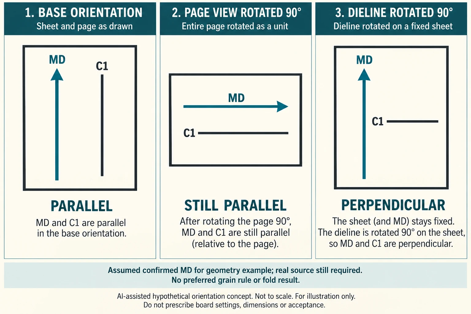
A rotated screenshot can look like a grain change even when the physical relationship is unchanged. Use an idealized geometry comparison before asking the converter to revise the sheet layout. Assume, only for this example, that a confirmed machine-direction arrow points up and crease C1 is vertical. Their relationship is parallel; no performance preference follows from that description.
Scroll horizontally if columns extend beyond the view.
| Hypothetical configuration | Named object | Relationship | Input or next scope |
|---|---|---|---|
| BASE20 | C1 | relation | MD20; PARALLEL |
| BASE20 | BASE20 | rotates | DIELINE_ON_FIXED_SHEET; 0 degrees |
| PAGE_VIEW20 | C1 | relation | MD20; PARALLEL |
| PAGE_VIEW20 | PAGE_VIEW20 | rotates | WHOLE_VIEW; 90 degrees |
| SHEET_LAYOUT20 | C1 | relation | MD20; PERPENDICULAR |
| SHEET_LAYOUT20 | SHEET_LAYOUT20 | rotates | DIELINE_ON_FIXED_SHEET; 90 degrees |
In PAGE_VIEW20 the whole drawing view rotates ninety degrees: the MD arrow and C1 both become horizontal. They remain parallel. In the separate SHEET_LAYOUT20 proposal, the MD arrow stays up on the fixed sheet while the dieline alone rotates ninety degrees. C1 becomes horizontal and its relationship to MD becomes perpendicular. These are different operations, not consecutive manufacturing instructions. The CSV gives each its own configuration, arrow orientation, crease orientation, relationship and numeric rotation with degrees as the unit.
Ask the designer which operation occurred. If only the page view changed, preserve the crease-to-MD relationship while recording the new viewing orientation. If the proposed cutting layout changed, ask the converter to confirm the physical sheet direction and identify the creases requiring another formed-sample review. A visual page rotation alone is insufficient evidence for either manufacturing conclusion.
The original C1 lid/rear-wall, C2 base/front-wall and C3 side/corner records remain independent. The geometric example neither selects a preferred grain direction nor predicts cracking or fold resistance. Actual grade, supplied sheet identity, sourced direction, tool proposal and intended forming action are still required for a construction-specific answer. An unconfirmed real arrow remains unconfirmed even if the teaching example uses a clean orientation.
Download the paperboard grain crease direction map record (.csv). It includes the original table fields and scenarios alongside the added relationships. HYPOTHETICAL rows are editorial examples or required review scopes, not actual records. Actual quantity, configuration, component and file identities, materials, process, specification, copy, method, condition, observation, owner, decision, evidence and dates are blank. ACTUAL_BLANK is a separate empty starting row; enter permitted project evidence before using an actual record. A blank means unknown.
Use the Packaging Dieline Changes Need an Impact Record for its separate question. Use the Packaging Print Finishes: A Supplier Brief Checklist for its separate question.
References apply to the materials, processes or guidance named in each source. Worked configurations and dimensions are teaching examples, not tested specifications or production limits. Use the project’s material specification, drawing and formed sample for approval.
Discuss this packaging specification with Packrivo. We coordinate independent suppliers. MOQ: 500 pieces per product/design; illustrative quantities are not production offers. Confirm materials, samples, price and timing for your project.