
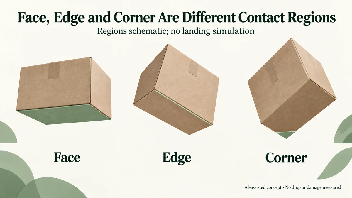
A carton landing on its bottom face introduces an impact through a different region from the same carton landing on an edge or corner. The contact location changes which packaging parts first deform and how motion and forces can reach the contents.
For a glass candle pack, a result from one orientation therefore cannot establish protection in every orientation. The useful design question is which part receives the impact and which supports connect that part to the product.
Face, edge and corner contact involve different geometry
In an ideal face-first contact, a comparatively broad outer panel approaches the landing surface. An edge-first contact begins around the meeting line of two panels. Corner-first contact begins around the meeting region of three panels.
Those descriptions locate the initial contact. They are not fixed contact areas or predictions of impact force. Real carton corners are rounded, folded and joined; the contact can spread as the structure deforms.
A landing near one corner can also introduce rotation or an uneven response if its reaction is offset from the packed system’s centre of mass. The product’s restraint and the carton construction determine what happens next. Orientation alone does not prescribe a damage outcome.
The distinction gives a buyer something more useful than a general request for a stronger box: identify the entry region and the route from that region to the contents.
The support that works at the base may not serve the upper corner
Suppose a glass jar rests on an intended base support inside a retail box, which sits in an outer carton. A bottom-face impact first acts through the carton base and the parts between that base and the jar.
An upper-corner impact starts elsewhere. It can involve upper panels, joints, nearby clearances and restraint contacts before the base support participates in the same way.
A base pad may remain useful, but its visible thickness does not show how the jar is restrained in that second event. Similarly, an open-box photograph can reveal the bottom support while hiding the lid-side arrangement.
Review the packed product with its lid, accessories and closures included. A jar lid approaching the presentation-box roof presents a different contact from the jar base meeting its holder. These paths should remain separately identifiable.
The candle glass contact guide locates those physical relationships. Impact orientation adds a direction and an entry region to that contact map; the map itself is not a drop result.
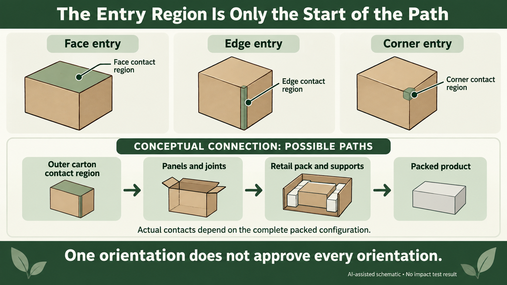
Follow two hypothetical landings of the same pack
Consider one invented candle configuration with a bottom holder and an unresolved upper clearance. No carton was dropped and no glass damage was observed.
In the first explanatory view, the outer carton lands bottom-face first. The drawing can trace a possible route from the bottom panel through the retail-box base and holder toward the jar.
In the second view, that same packed design approaches the surface at an upper corner. The drawing now needs to identify that corner, the nearby panel interfaces and the parts that may meet as the pack responds.
The contents must rotate with the carton in the second view. Keeping the jar upright on the page while turning only the outer outline would illustrate a different packing arrangement, not simply a different landing orientation.
Neither drawing establishes which landing is more severe. It explains why a bottom-support proposal cannot be accepted for every contact route merely because it looks adequate in the first view.
If the design changes to add an upper restraint, that creates a new packed configuration. It can change the jar’s contact and removal conditions as well as its response to an impact. Those effects need review together.
A free-fall method and a protection claim have different scope
The public catalogue for ASTM D5276-19(2023) concerns free-fall drop testing of loaded containers. It describes evaluation of the container and inner packing in protecting contents under a drop impact.
That scope does not supply a universal drop height or sequence for decorative gift packs. The complete procedure, relevant distribution objective and acceptance requirements still belong with the responsible evaluator.
A report should identify its actual loaded configuration and tested orientations. A test photograph showing one face does not establish that an edge or corner was included. Equally, a recorded corner result should not be relabelled as proof of every other orientation.
Use the distribution-test scope guide to define the assembled system and objective. This article helps explain why orientation is one of the physical inputs, rather than selecting a test programme for the buyer.
Use orientation to locate the unanswered design question
For a proposed pack, draw the intended product position and name the outer face, edge or corner under discussion. Follow the possible contact route through the relevant panels, supports and product surfaces.
Where that route is unclear, obtain the missing structural view before treating a bottom pad, thicker carton or tighter cavity as the answer. The same outer size can conceal different internal support paths.
If damage has already been received, the damage-location record preserves what was actually seen. A damaged corner does not prove that the shipment experienced the hypothetical corner-first landing described here.
Packrivo can coordinate those construction and supplier questions. The protection decision needs relevant evidence for the actual complete package and the orientations within its agreed evaluation scope.
Source scope: ASTM D5276-19(2023) was listed active with catalogue update 4 October 2023, checked 11 October 2026. Only the public scope and significance information were consulted; the paid full method was not read. The two landings are original schematic examples, without measured acceleration, damage, height or transport performance.
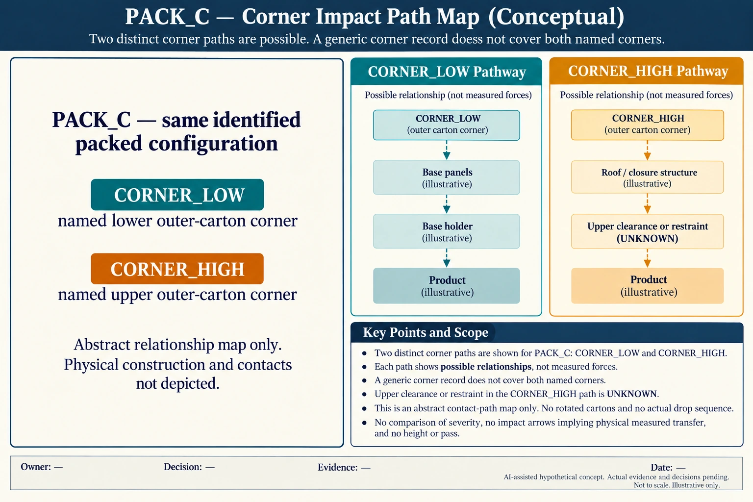
Two named corners can lead into different support paths
Name two outer regions in one invented packed configuration: CORNER_LOW near the base support and CORNER_HIGH near an unresolved upper clearance. A description saying only “corner” does not identify which region or connected components an evaluation covered. The paths are schematic possibilities, not observed impacts.
Scroll horizontally if columns extend beyond the view.
| Hypothetical configuration | Named object | Relationship | Input or next scope |
|---|---|---|---|
| CORNER_LOW | CORNER_LOW | part of | PACK_C |
| CORNER_LOW | CORNER_LOW | possible contact path to | BASE_PANELS |
| CORNER_LOW | BASE_PANELS | possible contact path to | BASE_HOLDER |
| CORNER_LOW | BASE_HOLDER | possible contact path to | PRODUCT |
| CORNER_HIGH | CORNER_HIGH | part of | PACK_C |
| CORNER_HIGH | CORNER_HIGH | possible contact path to | ROOF_CLOSURE |
| CORNER_HIGH | ROOF_CLOSURE | possible contact path to | UPPER_CLEARANCE_RESTRAINT_UNKNOWN |
| CORNER_HIGH | UPPER_CLEARANCE_RESTRAINT_UNKNOWN | possible contact path to | PRODUCT |
| PACK_C | GENERIC_CORNER_RECORD | does not identify | BOTH_LOW_AND_HIGH_REGIONS |
| PACK_C | PATH_MAP | does not establish | SEVERITY_DROP_SEQUENCE_OR_PROTECTION |
The lower region can be discussed through the base panels and base-holder relationship. The upper region instead raises roof, closure and upper-restraint questions. Do not transfer a record for CORNER_LOW to CORNER_HIGH simply because both use the same word. Their severity and actual response remain unassigned.
The new figure is a relationship map, not a rotated-box drawing. Any actual orientation views must rotate the whole packed configuration consistently, including its contents. A changed upper restraint would create another configuration with its own contact and removal implications.
Ask which named region, complete loaded configuration and orientation the evidence concerns. D5276’s public 110 lb (50 kg) statement is tied to named ISO correspondence, not a universal maximum for all use of the method. No drop height, sequence, damage level or transport approval follows from this map.
Download the parcel corner identity contact load path scope record (.csv). It includes the original table fields and scenarios alongside the added relationships. HYPOTHETICAL rows are editorial examples or required review scopes, not actual records. Actual quantity, configuration, component and file identities, materials, process, specification, copy, method, condition, observation, owner, decision, evidence and dates are blank. ACTUAL_BLANK is a separate empty starting row; enter permitted project evidence before using an actual record. A blank means unknown.
Use the Glass Candle Packaging: Map Contact Before Approval for its separate question. Use the Packaging Distribution Tests: Define the Packed System for its separate question.
Source scope checked 17 October 2026: ASTM D5276-19(2023) public scope concerns loaded-container free fall. Its 110 lb (50 kg) wording describes named ISO correspondence, not a universal maximum for every application. No paid method, actual impact, height, damage or transport performance was established. The added configurations and calculations are hypothetical, with actual evidence and decisions pending.
Discuss this packaging specification with Packrivo. We coordinate independent suppliers. MOQ: 500 pieces per product/design; illustrative quantities are not production offers. Confirm materials, samples, price and timing for your project.