
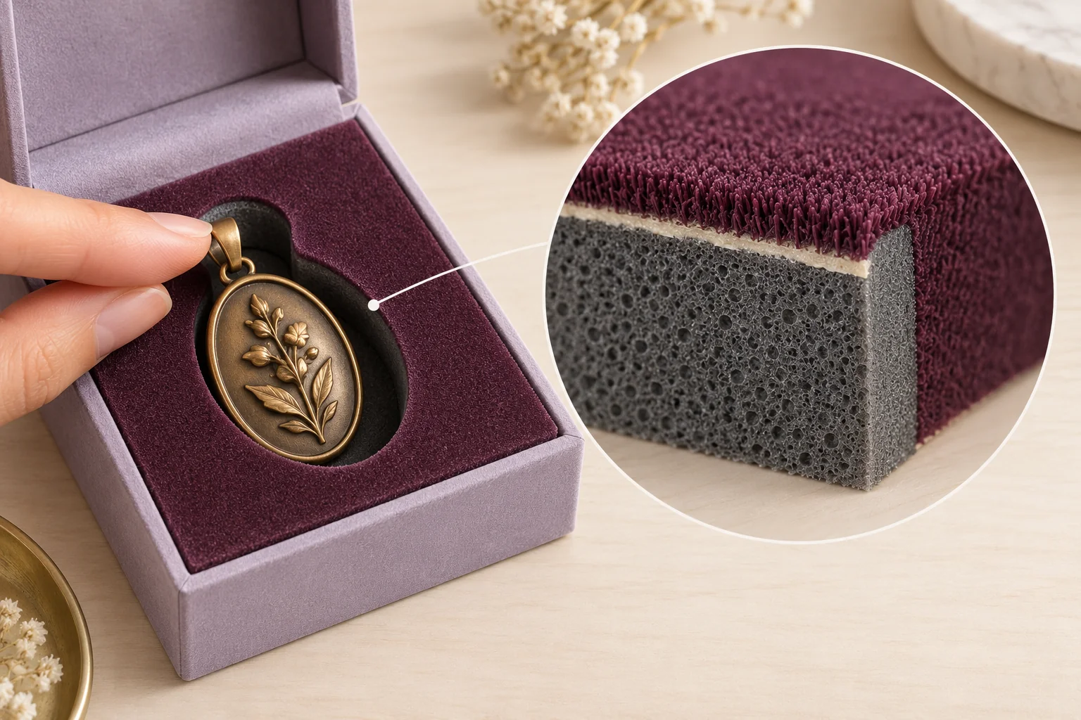
The concept illustrates a layered holder. Actual base grade, flock construction and cavity interfaces are confirmed for the project.
Name the layer on each actual face
Request a description of the proposed flocked surface, foam base, cut edges and any joining layers. Record which face would contact the actual gift and which surface remains exposed. A proposed layer description does not establish scratch resistance or the behavior of a finished gift on the offered holder.
Request the base foam grade, thickness and actual flock/adhesive construction. Mark which faces carry the layer and which cavity walls or edges remain exposed. Keep any lining, backing or attachment component in the same BOM.
Supply the actual product finish and permitted contact areas. Locate the intended removal grip beside the flock termination and cut edge. A top view of a covered face cannot show all the interfaces the product passes during loading or lift.
Review the layer termination at the product route
Load the actual product and observe its path into and out of the cavity. Inspect the exposed cut wall and the point where the layer ends. Record visible fibers, marks or another observation with its location, sample identity and conditions; retain any cause or performance question separately.
Compare the depth-cut PU bed or through-cut EVA holder through their own offered interfaces. A flocked-face proposal adds layer/BOM and termination questions; its base material remains a named supplier proposal rather than automatically EVA.
If the converter proposes a changed layer, edge or grip, keep that change attached to the earlier observation. Review the same finished product or explicitly name a substitute. The buyer needs to see which surface construction was actually compared.
Use a face, layer and cut-edge record
This original hypothetical jewelry-holder table distinguishes visible faces from exposed interfaces.
| Surface/interface | Example input | Evidence to return |
|---|---|---|
| Base F1 | Actual proposed foam grade and thickness | Current grade/BOM reference |
| Layer L1 | Flock/adhesive on named upper faces | Supplier layer and face map |
| Termination E1 | Edge beside the product cavity | Actual section and close-up |
| Cut wall C1 | Exposed base or offered edge treatment | Located product-contact observation |
| Grip G1 | Intended lift beside E1/C1 | Actual loading/removal sequence |
Keep the surface question with the holder choice
The converter identifies the layer and exposed edges. The buyer supplies finish restrictions, while the packing observer returns located handling evidence. The buyer then decides whether the termination, contact or grip needs another proposed construction.
Use the current die-cut holder option, inserts hub and material decision method as the real internal route. The sample revision record links any changed layer to its actual evidence.
Send the face/BOM map, finished product and unresolved edge/contact question through Get a Quote. MOQ is 500 pieces per design; offered materials, sample scope and commercial terms are confirmed for the project.