
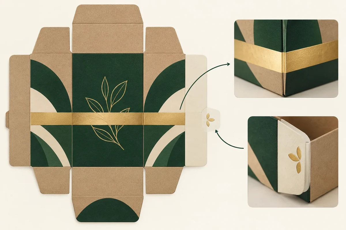
Map each proposed foil element against the current fold lines and glue areas before artwork approval. Identify the foil process, material and nearby interface, then ask the printer to confirm the proposal. Keep any required separation as a supplier-specific decision rather than adding a universal distance to the file.
This map is useful after a reflective treatment has been chosen. Its job is to expose the few places where that artwork meets the construction. It doesn’t replace the printer’s production specification.
Name the foil process before mapping it
The Foil & Specialty Effects Association’s foil process guide distinguishes hot, cold and digital techniques. That distinction supports asking which process is proposed. It doesn’t establish the same restrictions for all processes or substrates.
Record the selected printer’s process name, substrate and surface treatment. If those are undecided, mark the placement map as provisional. A metallic-looking mock-up cannot identify the manufacturing process.
Use the finish choice guide if the desired effect is still open. This method begins when the specific foil artwork needs a construction review.
Map elements and interfaces on the current dieline
Give each foil element a stable ID, such as F1 for a front motif and F2 for a lid border. Place those IDs on the artwork layer without changing the structural lines. Keep a named dieline revision beside the map.
For each element, identify the nearest fold, cut or glue interface that needs discussion. A crossing element and a nearby element are different cases. Mark the relationship rather than assuming the same margin covers both.
Ask the printer or converter to confirm glue areas on the proposed construction. A designer should not infer every glue area from the flat outline. Show any supplier-confirmed region clearly and preserve the original structural file.
Write the desired appearance in the formed state. A border may need to read across two panels, while a small motif may stay entirely on one face. Those requests give the printer context for its response.
Use a foil conflict map
Keep the map as a short drawing attachment and a response table. Each row needs one located relationship and one next action.
The entries below are hypothetical, not observed production results. Record the drawing and artwork revisions, proposed process, substrate, response owner and evidence references above the table.
| Foil / interface | Proposed relationship | Question for printer or converter | Decision status |
|---|---|---|---|
| F1–C1 | Sleeve border F1 crosses crease C1 | Can this artwork be used at C1 with the named process and material? What sample review is needed? | Open: process review and formed appearance |
| F1–G1 | The same border approaches provisional joining region G1 | Please confirm G1 on this construction. Does the seam-side segment require a change? | Open: joining region confirmation and artwork decision |
Record a supplier-requested margin with its source and scope. If the process changes later, ask whether that instruction still applies rather than carrying it across automatically.
Follow a hypothetical sleeve border
Suppose a brand proposes a foil border across the front and side of a folding sleeve. The border crosses a crease, and another part approaches the prepared seam. The buyer creates two rows because the relationships are different.
The printer is asked to review the crease crossing for the proposed material and process. The seam row asks whether the foil artwork conflicts with the confirmed joining area. No universal number is inserted before those replies arrive.
If the converter confirms G1 and requests moving only the seam-side segment, the designer prepares a revised artwork file. Mark F1–G1 as revised, awaiting confirmation against that file. F1–C1 stays open until its separate review is completed; if the revision changes the crossing at C1, review that relationship against the new file too. That makes approval specific rather than calling the entire foil layer approved after one correction.
Record each printer response as a scoped instruction
In the hypothetical sleeve map, the same border F1 crosses crease C1 and approaches joining region G1. Record F1–C1 and F1–G1 as separate relationships, each with its own response and decision status. A printer instruction about G1 should not automatically be copied onto C1 because both are close to the same foil border.
When a source gives a separation requirement, record the exact proposed process, substrate and drawing revision it covers. Keep the original reply attached. A margin may become irrelevant after the foil process or seam construction changes, so the scope needs to travel with the instruction.
Ask a located question: ‘Please review border F1 against confirmed region G1 for this foil and sleeve proposal.’ A reply asking the designer to move the seam-side segment of F1 should be reflected in the artwork revision and the F1–G1 row. If G1 is still only a provisional region, retain that uncertainty.
For the formed sample, keep position and surface appearance decisions separate. The motif can occupy the agreed location while its physical effect still needs review. Record which decision the sample closes and which remains open. This makes the map useful at handoff without turning a supplier’s local instruction into an unsupported general rule.
Close placement with formed evidence
Review the foil on the formed component in the intended light and orientation. A digital layer proof can show position, while the physical sample shows the proposed surface result. Keep those approvals distinct.
The artwork handoff checklist helps attach the final map to the current file. Send unresolved element IDs and supplier replies through the packaging enquiry. The next action should name the element and interface that still needs confirmation.
Reopen both relationships when the foil process changes
A new hypothetical alternative changes a proposed hot-foil process HOT_r1 to a digital process DIGITAL_r2. Keep F1–C1, the crease crossing, and F1–G1, the joining-area relationship, as separate records under each proposal. No process has been selected or qualified.
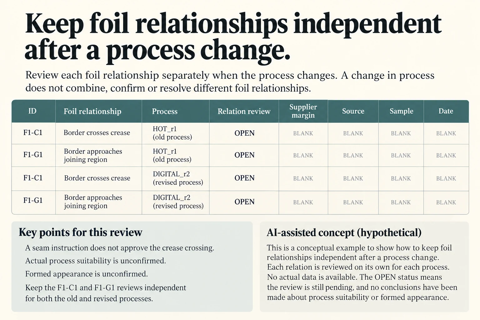
Scroll horizontally if columns extend beyond the view.
| Scenario scope | Exact object or route | Hypothetical input or output | Calculation or record boundary |
|---|---|---|---|
| Process scoped relation | HOT_r1_F1_C1 | Unobserved; actual fields blank | Fictional process proposal; independent margin/source/formed sample and decision remain unknown |
| Process scoped relation | HOT_r1_F1_G1 | Unobserved; actual fields blank | Fictional process proposal; independent margin/source/formed sample and decision remain unknown |
| Process scoped relation | DIGITAL_r2_F1_C1 | Unobserved; actual fields blank | Fictional process proposal; independent margin/source/formed sample and decision remain unknown |
| Process scoped relation | DIGITAL_r2_F1_G1 | Unobserved; actual fields blank | Fictional process proposal; independent margin/source/formed sample and decision remain unknown |
The earlier seam-side instruction belongs to its stated process, material and drawing. A process change cannot silently carry that instruction onto the new route, and one F1–G1 response does not approve F1–C1. Keep any requested separation, source and sample reference empty until the responsible printer supplies them.
Retain the original conditional artwork revision as history. If the revised border also changes the crossing, reopen that specific relationship. A formed position decision and the physical reflective appearance remain different questions even after the flat layer is located correctly.
Download the packaging foil placement folds glue record (.csv). It covers the original scenarios and this added comparison. HYPOTHETICAL rows are invented planning examples. Actual quantity, value, configuration, method, owner, observation, condition, decision, evidence and dates are blank because no actual project record has been obtained. Copy a relevant row and replace its type with ACTUAL only when entering permitted project evidence; keep the example and actual record separate. ACTUAL_BLANK is an empty starting row. A blank is unknown, never approval.
The related Foil, Embossing or Spot UV: Choose by the Effect Needed guide concerns a separate requirement. Use this record for the specific comparison above rather than treating that guide as evidence of a completed result.
Follow affected structural and layout decisions with the drawing change impact record. Keep the actual appearance reference separate with the physical color comparison.
References retain their stated general-guidance or manufacturer-example scope. Worked figures and records are teaching examples, not observed orders, stock, prices or measured performance.
Discuss this packaging specification with Packrivo. We coordinate independent suppliers. MOQ: 500 pieces per product/design; illustrative quantities are not production offers. Confirm materials, samples, price and timing for your project.