
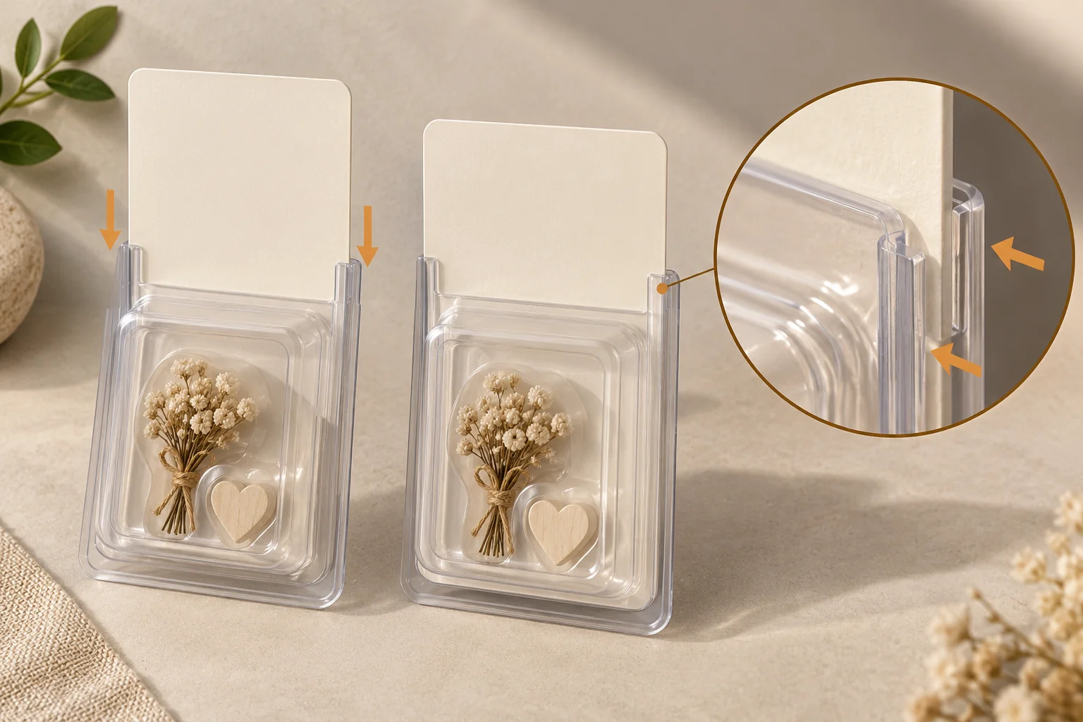
The concept shows a proposed card-retaining channel; the actual formed blister and card specification are confirmed by the converter.
Draw where the card enters and stops
The slide-blister construction description identifies flanges that fold around the back to receive a sliding card. Use this narrow construction reference to request the offered channel drawing. It does not determine every blister’s resin, seal or card dimension.
Label the entry edge, retaining sides and stop location. Supply the card’s finished size, proposed caliper and printing faces. Mark the copy or identity that must remain visible once the card is seated. A card artwork PDF should be tied to the actual channel outline.
Provide the accessory in its final packed state, including any mounting attachment or inner wrap. Locate projections beside the channel and card path. State whether the product is placed before the card, held by the card or positioned through another offered assembly step.
Review assembly and withdrawal as separate actions
Load the accessory through the confirmed sequence and slide the proposed card into the channel. Observe the entry, stop and edge seating with the actual formed pack. Record a catching edge, displaced product or copy hidden beneath a flange at its specific location.
Then review the customer’s opening route. Specify whether the card slides out completely, releases through a grip or uses another offered action. Keep the card and product together during that review so the access question remains visible.
Compare the mounting card holder when the product can be presented on a card without a formed retaining enclosure. The multi-cavity tray is another holder arrangement with different loading and removal fields. The sliding card interface should be the reason for this configuration.
Use a card-channel handoff table
The hypothetical jewelry-accessory record below separates the channel, card and product.
| Interface | Example brief entry | Next confirmation |
|---|---|---|
| Entry edge E1 | Card is inserted from the named side | Channel drawing and assembly order |
| Card C1 | Finished card, caliper proposal and print faces | Card revision linked to outline |
| Retaining flange F1 | Offered edge covering the card | Visible-copy and edge-seating review |
| Product cavity | Accessory in its final wrapped state | Loaded channel/cavity contact view |
| Opening grip | Intended card withdrawal point | Customer removal observation |
Keep the card drawing with the formed proposal
The converter should return the channel and stop geometry plus the offered sheet and card identities. The packing owner should demonstrate the assembly sequence. The buyer can then approve the visible information and customer access or ask for a different retention/opening proposal.
Use the artwork handoff guide to connect the card output to the accepted outline. The existing thermoformed insert option helps compare the broader holder role.
Send the product state, card/channel map and withdrawal question through Get a Quote. MOQ is 500 pieces per design; geometry, materials, samples and commercial terms are confirmed against the project.